

Category: Microsoft
Category Archives: Microsoft

A Practical Guide to Zone Redundant AKS Clusters and Storage
Resilience is a critical aspect of any modern application infrastructure. When failures occur, a resilient solution is capable of recovering quickly and maintaining functionality. To enhance the intra-region resiliency of an Azure Kubernetes Service (AKS) cluster, creating a zone redundant cluster is of utmost importance. This article explains how you can create a zone redundant AKS cluster and the implications of each approach on the deployment strategy and configuration of the persistent volumes used by the workloads. Here
re you can find the companion code for this article.
Prerequisites
An active Azure subscription. If you don’t have one, create a free Azure account before you begin.
Visual Studio Code installed on one of the supported platforms along with the HashiCorp Terraform.
Azure CLI version 2.56.0 or later installed. To install or upgrade, see Install Azure CLI.
aks-preview Azure CLI extension of version 0.5.140 or later installed
The deployment must be started by a user who has sufficient permissions to assign roles, such as a User Access Administrator or Owner.
Your Azure account also needs Microsoft.Resources/deployments/write permissions at the subscription level.
Availability Zones
Availability Zones are separate groups of datacenters in a region. They are located close enough to have fast connections to each other, with a round-trip latency of less than 2ms. However, they are also far enough apart to minimize the chances of all zones being affected by local issues or bad weather. Each availability zone has its own power, cooling, and networking systems. If one zone goes down, the other zones can still support regional services, capacity, and high availability. This setup helps ensure that your data remains synchronized and accessible even during unexpected events. The diagram below illustrates examples of Azure regions, with Regions 1 and 2 being equipped with availability zones.
Not all the Azure regions support availability zones. For more information on which regions support Availability Zones, you can refer to the Availability zone service and regional support documentation.
Azure services with availability zone support
Azure is continuously expanding its range of services that support availability zones. These services can be divided into three types: zonal, zone-redundant, and always-available.
Zonal services allow you to deploy resources to a specific availability zone of your choice, ensuring optimal performance and low latency. Resiliency is achieved by replicating applications and data across multiple zones within the same region. For example, you can align the agent nodes of an AKS node pool and the managed disks created via persistent volume claims to a specific zone, increasing resilience by deploying multiple instances of resources across different zones.
Zone-redundant services automatically distribute or replicate resources across multiple availability zones. This ensures that even if one zone fails, the data remains highly available. For instance, you can create a zone-redundant VMSS-based node pool where the nodes are spread across availability zones within a region.
Always-available services are resilient to both zone-wide and region-wide outages. These services are available across all Azure geographies and provide uninterrupted availability. For a comprehensive list of always-available services, also known as non-regional services, you can refer to the Products available by region documentation on Azure.
Maximizing Resilience with Availability Zones
By utilizing Availability Zones, the resilience of an AKS cluster can be greatly improved. When creating an AKS cluster, spreading the AKS agent nodes across multiple zones can enhance the cluster’s resilience within a region. This involves distributing AKS agent nodes across physically separate data centers, ensuring that nodes in one pool continue running even if another zone encounters failures. If co-locality requirements exist, there are two options available:
Regular VMSS-based AKS Deployment: This involves deploying the AKS cluster or one of its node pools into a single Availability Zone, ensuring proximity and minimizing internode latency.
Proximity Placement Groups: Proximity Placement Groups (PPG) can be utilized to minimize internode latency while maintaining zone redundancy. Nodes within a PPG are placed in the same data center, ensuring optimal communication and minimizing latency.
Creating Zone Redundant AKS Clusters
There are two approaches to creating a zone redundant AKS cluster:
Zone Redundant Node Pool: Another approach involves creating a zone redundant node pool, where nodes are spread across multiple Availability Zones. This ensures that the node pool can withstand failures in any zone while maintaining the desired functionality.
AKS Cluster with three Node Pools: In this approach, an AKS cluster is created with three node pools, each assigned to a different availability zone. This ensures that the cluster has redundancy across zones.
Let’s explore the implications on workload deployment strategy and storage configuration for these two strategies.
Azure Storage redundancy
Azure Storage always stores three copies of your data so that your information is protected from planned and unplanned events, including transient hardware failures, network or power outages, and massive natural disasters. Redundancy ensures that your storage account meets its availability and durability targets even in case of failures.
When deciding which redundancy option is best for your scenario, consider the tradeoffs between lower costs and higher availability. The factors that help determine which redundancy option you should choose include:
How your data is replicated within the primary region.
Whether your data is replicated to a second region that is geographically distant to the primary region, to protect against regional disasters (geo-replication).
Whether your application requires read access to the replicated data in the secondary region if the primary region becomes unavailable for any reason (geo-replication with read access).
Data in Azure Storage is always replicated three times in the primary region. Azure Storage offers two options for how your data is replicated in the primary region: locally redundant storage (LRS) and zone-redundant storage (ZRS). For more information, see Azure Storage redundancy.
Locally redundant storage (LRS)
Locally redundant storage (LRS) is the lowest-cost redundancy option and offers the least durability compared to other options. LRS protects your data against server rack and drive failures. However, if a disaster such as fire or flooding occurs within the data center, all replicas of a storage account using LRS may be lost or unrecoverable. To mitigate this risk, Microsoft recommends using zone-redundant storage (ZRS), geo-redundant storage (GRS), or geo-zone-redundant storage (GZRS). A write request to a storage account that is using LRS happens synchronously. The write operation returns successfully only after the data is written to all three replicas. The following diagram shows how your data is replicated within a single data center with LRS:
A LRS managed disk can only be attached and used by a virtual machine located in the same availability zone. LRS is a good choice for the following scenarios:
If your application stores data that can be easily reconstructed if data loss occurs, you may opt for LRS.
If your application is restricted to replicating data only within a country or region due to data governance requirements, you may opt for LRS. In some cases, the paired regions across which the data is geo-replicated may be in another country or region. For more information on paired regions, see Azure regions.
If your scenario is using Azure unmanaged disks, you may opt for LRS. While it’s possible to create a storage account for Azure unmanaged disks that uses GRS, it isn’t recommended due to potential issues with consistency over asynchronous geo-replication.
LRS is the redundancy model used by the built-in storage classes in Azure Kubernetes Service (AKS), such as managed-csi and managed-csi-premium. For more information, see Use the Azure Disk Container Storage Interface (CSI) driver in Azure Kubernetes Service (AKS).
Zone-redundant storage (ZRS)
Zone-redundant storage (ZRS) replicates your storage account synchronously across three Azure availability zones in the primary region. Each availability zone is a separate physical location with independent power, cooling, and networking. ZRS offers durability for storage resources of at least 99.9999999999% (12 9’s) over a given year. With ZRS, your data is still accessible for both read and write operations even if a zone becomes unavailable. If a zone becomes unavailable, Azure undertakes networking updates, such as DNS repointing. These updates may affect your application if you access data before the updates have completed. When designing applications for ZRS, follow practices for transient fault handling, including implementing retry policies with exponential back-off.
A write request to a storage account that is using ZRS happens synchronously. The write operation returns successfully only after the data is written to all replicas across the three availability zones. If an availability zone is temporarily unavailable, the operation returns successfully after the data is written to all available zones. Microsoft recommends using ZRS in the primary region for scenarios that require high availability. ZRS is also recommended for restricting replication of data to a particular country or region to meet data governance requirements. Microsoft recommends using ZRS for Azure Files workloads. If a zone becomes unavailable, no remounting of Azure file shares from the connected clients is required.
The following diagram shows how your data is replicated across availability zones in the primary region with ZRS:
ZRS provides excellent performance, low latency, and resiliency for your data if it becomes temporarily unavailable. However, ZRS by itself may not protect your data against a regional disaster where multiple zones are permanently affected. For protection against regional disasters, Microsoft recommends using geo-zone-redundant storage (GZRS), which uses ZRS in the primary region and also geo-replicates your data to a secondary region.
The archive tier for Blob Storage isn’t currently supported for ZRS, GZRS, or RA-GZRS accounts. Unmanaged disks don’t support ZRS or GZRS. For more information about which regions support ZRS, see Azure regions with availability zones.
Zone-redundant storage for managed disks
Zone-redundant storage (ZRS) synchronously replicates your Azure managed disk across three Azure availability zones in the region you select. Each availability zone is a separate physical location with independent power, cooling, and networking. ZRS disks provide at least 99.9999999999% (12 9’s) of durability over a given year. A ZRS managed disk can be attached by a virtual machines in a different availability zone. ZRS disks are currently not available an all the Azure regions. For more information on ZRS disks, see Zone Redundant Storage (ZRS) option for Azure Disks for high availability
AKS cluster with Zone-Redundant Node Pools
The first strategy entails deploying an AKS cluster with zone-redundant node pools, where the nodes are distributed evenly across the availability zones within a region. The diagram below illustrates an AKS cluster with a zone-redundant system-mode node pool and a zone-redundant user-mode node pool.
Deploy an AKS cluster with Zone-Redundant Node Pools using Azure CLI
When creating a cluster using the az aks create command, the –zones parameter allows you to specify the availability zones for deploying agent nodes. Here’s an example that demonstrates creating an AKS cluster, with a total of three nodes. One node is deployed in zone 1, another in zone 2, and the third in zone 3. For more information, see Create an AKS cluster across availability zones.
# Variables
source ./00-variables.sh
# Check if the resource group already exists
echo “Checking if [“$resourceGroupName”] resource group actually exists in the [$subscriptionName] subscription…”
az group show –name $resourceGroupName –only-show-errors &>/dev/null
if [[ $? != 0 ]]; then
echo “No [“$resourceGroupName”] resource group actually exists in the [$subscriptionName] subscription”
echo “Creating [“$resourceGroupName”] resource group in the [$subscriptionName] subscription…”
# create the resource group
az group create
–name $resourceGroupName
–location $location
–only-show-errors 1>/dev/null
if [[ $? == 0 ]]; then
echo “[“$resourceGroupName”] resource group successfully created in the [$subscriptionName] subscription”
else
echo “Failed to create [“$resourceGroupName”] resource group in the [$subscriptionName] subscription”
exit -1
fi
else
echo “[“$resourceGroupName”] resource group already exists in the [$subscriptionName] subscription”
fi
# Check if log analytics workspace exists and retrieve its resource id
echo “Retrieving [“$logAnalyticsName”] Log Analytics resource id…”
az monitor log-analytics workspace show
–name $logAnalyticsName
–resource-group $resourceGroupName
–query id
–output tsv
–only-show-errors &>/dev/null
if [[ $? != 0 ]]; then
echo “No [“$logAnalyticsName”] log analytics workspace actually exists in the [“$resourceGroupName”] resource group”
echo “Creating [“$logAnalyticsName”] log analytics workspace in the [“$resourceGroupName”] resource group…”
# Create the log analytics workspace
az monitor log-analytics workspace create
–name $logAnalyticsName
–resource-group $resourceGroupName
–identity-type SystemAssigned
–sku $logAnalyticsSku
–location $location
–only-show-errors
if [[ $? == 0 ]]; then
echo “[“$logAnalyticsName”] log analytics workspace successfully created in the [“$resourceGroupName”] resource group”
else
echo “Failed to create [“$logAnalyticsName”] log analytics workspace in the [“$resourceGroupName”] resource group”
exit -1
fi
else
echo “[“$logAnalyticsName”] log analytics workspace already exists in the [“$resourceGroupName”] resource group”
fi
# Retrieve the log analytics workspace id
workspaceResourceId=$(az monitor log-analytics workspace show
–name $logAnalyticsName
–resource-group $resourceGroupName
–query id
–output tsv
–only-show-errors 2>/dev/null)
if [[ -n $workspaceResourceId ]]; then
echo “Successfully retrieved the resource id for the [“$logAnalyticsName”] log analytics workspace”
else
echo “Failed to retrieve the resource id for the [“$logAnalyticsName”] log analytics workspace”
exit -1
fi
# Check if the client virtual network already exists
echo “Checking if [$virtualNetworkName] virtual network actually exists in the [$resourceGroupName] resource group…”
az network vnet show
–name $virtualNetworkName
–resource-group $resourceGroupName
–only-show-errors &>/dev/null
if [[ $? != 0 ]]; then
echo “No [$virtualNetworkName] virtual network actually exists in the [$resourceGroupName] resource group”
echo “Creating [$virtualNetworkName] virtual network in the [$resourceGroupName] resource group…”
# Create the client virtual network
az network vnet create
–name $virtualNetworkName
–resource-group $resourceGroupName
–location $location
–address-prefixes $virtualNetworkAddressPrefix
–subnet-name $systemSubnetName
–subnet-prefix $systemSubnetPrefix
–only-show-errors 1>/dev/null
if [[ $? == 0 ]]; then
echo “[$virtualNetworkName] virtual network successfully created in the [$resourceGroupName] resource group”
else
echo “Failed to create [$virtualNetworkName] virtual network in the [$resourceGroupName] resource group”
exit -1
fi
else
echo “[$virtualNetworkName] virtual network already exists in the [$resourceGroupName] resource group”
fi
# Check if the user subnet already exists
echo “Checking if [$userSubnetName] user subnet actually exists in the [$virtualNetworkName] virtual network…”
az network vnet subnet show
–name $userSubnetName
–vnet-name $virtualNetworkName
–resource-group $resourceGroupName
–only-show-errors &>/dev/null
if [[ $? != 0 ]]; then
echo “No [$userSubnetName] user subnet actually exists in the [$virtualNetworkName] virtual network”
echo “Creating [$userSubnetName] user subnet in the [$virtualNetworkName] virtual network…”
# Create the user subnet
az network vnet subnet create
–name $userSubnetName
–vnet-name $virtualNetworkName
–resource-group $resourceGroupName
–address-prefix $userSubnetPrefix
–only-show-errors 1>/dev/null
if [[ $? == 0 ]]; then
echo “[$userSubnetName] user subnet successfully created in the [$virtualNetworkName] virtual network”
else
echo “Failed to create [$userSubnetName] user subnet in the [$virtualNetworkName] virtual network”
exit -1
fi
else
echo “[$userSubnetName] user subnet already exists in the [$virtualNetworkName] virtual network”
fi
# Check if the pod subnet already exists
echo “Checking if [$podSubnetName] pod subnet actually exists in the [$virtualNetworkName] virtual network…”
az network vnet subnet show
–name $podSubnetName
–vnet-name $virtualNetworkName
–resource-group $resourceGroupName
–only-show-errors &>/dev/null
if [[ $? != 0 ]]; then
echo “No [$podSubnetName] pod subnet actually exists in the [$virtualNetworkName] virtual network”
echo “Creating [$podSubnetName] pod subnet in the [$virtualNetworkName] virtual network…”
# Create the pod subnet
az network vnet subnet create
–name $podSubnetName
–vnet-name $virtualNetworkName
–resource-group $resourceGroupName
–address-prefix $podSubnetPrefix
–only-show-errors 1>/dev/null
if [[ $? == 0 ]]; then
echo “[$podSubnetName] pod subnet successfully created in the [$virtualNetworkName] virtual network”
else
echo “Failed to create [$podSubnetName] pod subnet in the [$virtualNetworkName] virtual network”
exit -1
fi
else
echo “[$podSubnetName] pod subnet already exists in the [$virtualNetworkName] virtual network”
fi
# Check if the bastion subnet already exists
echo “Checking if [$bastionSubnetName] bastion subnet actually exists in the [$virtualNetworkName] virtual network…”
az network vnet subnet show
–name $bastionSubnetName
–vnet-name $virtualNetworkName
–resource-group $resourceGroupName
–only-show-errors &>/dev/null
if [[ $? != 0 ]]; then
echo “No [$bastionSubnetName] bastion subnet actually exists in the [$virtualNetworkName] virtual network”
echo “Creating [$bastionSubnetName] bastion subnet in the [$virtualNetworkName] virtual network…”
# Create the bastion subnet
az network vnet subnet create
–name $bastionSubnetName
–vnet-name $virtualNetworkName
–resource-group $resourceGroupName
–address-prefix $bastionSubnetPrefix
–only-show-errors 1>/dev/null
if [[ $? == 0 ]]; then
echo “[$bastionSubnetName] bastion subnet successfully created in the [$virtualNetworkName] virtual network”
else
echo “Failed to create [$bastionSubnetName] bastion subnet in the [$virtualNetworkName] virtual network”
exit -1
fi
else
echo “[$bastionSubnetName] bastion subnet already exists in the [$virtualNetworkName] virtual network”
fi
# Retrieve the system subnet id
systemSubnetId=$(az network vnet subnet show
–name $systemSubnetName
–vnet-name $virtualNetworkName
–resource-group $resourceGroupName
–query id
–output tsv
–only-show-errors 2>/dev/null)
if [[ -n $systemSubnetId ]]; then
echo “Successfully retrieved the resource id for the [$systemSubnetName] subnet”
else
echo “Failed to retrieve the resource id for the [$systemSubnetName] subnet”
exit -1
fi
# Retrieve the user subnet id
userSubnetId=$(az network vnet subnet show
–name $userSubnetName
–vnet-name $virtualNetworkName
–resource-group $resourceGroupName
–query id
–output tsv
–only-show-errors 2>/dev/null)
if [[ -n $userSubnetId ]]; then
echo “Successfully retrieved the resource id for the [$userSubnetName] subnet”
else
echo “Failed to retrieve the resource id for the [$userSubnetName] subnet”
exit -1
fi
# Retrieve the pod subnet id
podSubnetId=$(az network vnet subnet show
–name $podSubnetName
–vnet-name $virtualNetworkName
–resource-group $resourceGroupName
–query id
–output tsv
–only-show-errors 2>/dev/null)
if [[ -n $podSubnetId ]]; then
echo “Successfully retrieved the resource id for the [$podSubnetName] subnet”
else
echo “Failed to retrieve the resource id for the [$podSubnetName] subnet”
exit -1
fi
# Get the last Kubernetes version available in the region
kubernetesVersion=$(az aks get-versions
–location $location
–query “values[?isPreview==null].version | sort(@) | [-1]”
–output tsv
–only-show-errors 2>/dev/null)
# Create AKS cluster
echo “Checking if [“$aksClusterName”] aks cluster actually exists in the [“$resourceGroupName”] resource group…”
az aks show –name $aksClusterName –resource-group $resourceGroupName &>/dev/null
if [[ $? != 0 ]]; then
echo “No [“$aksClusterName”] aks cluster actually exists in the [“$resourceGroupName”] resource group”
echo “Creating [“$aksClusterName”] aks cluster in the [“$resourceGroupName”] resource group…”
# Create the aks cluster
az aks create
–name $aksClusterName
–resource-group $resourceGroupName
–service-cidr $serviceCidr
–dns-service-ip $dnsServiceIp
–os-sku $osSku
–node-osdisk-size $osDiskSize
–node-osdisk-type $osDiskType
–vnet-subnet-id $systemSubnetId
–nodepool-name $systemNodePoolName
–pod-subnet-id $podSubnetId
–enable-cluster-autoscaler
–node-count $nodeCount
–min-count $minCount
–max-count $maxCount
–max-pods $maxPods
–location $location
–kubernetes-version $kubernetesVersion
–ssh-key-value $sshKeyValue
–node-vm-size $nodeSize
–enable-addons monitoring
–workspace-resource-id $workspaceResourceId
–network-policy $networkPolicy
–network-plugin $networkPlugin
–service-cidr $serviceCidr
–enable-managed-identity
–enable-workload-identity
–enable-oidc-issuer
–enable-aad
–enable-azure-rbac
–aad-admin-group-object-ids $aadProfileAdminGroupObjectIDs
–nodepool-taints CriticalAddonsOnly=true:NoSchedule
–nodepool-labels nodePoolMode=system created=AzureCLI osDiskType=ephemeral osType=Linux
–nodepool-tags osDiskType=ephemeral osDiskType=ephemeral osType=Linux
–tags created=AzureCLI
–only-show-errors
–zones 1 2 3 1>/dev/null
if [[ $? == 0 ]]; then
echo “[“$aksClusterName”] aks cluster successfully created in the [“$resourceGroupName”] resource group”
else
echo “Failed to create [“$aksClusterName”] aks cluster in the [“$resourceGroupName”] resource group”
exit -1
fi
else
echo “[“$aksClusterName”] aks cluster already exists in the [“$resourceGroupName”] resource group”
fi
# Check if the user node pool exists
echo “Checking if [“$aksClusterName”] aks cluster actually has a user node pool…”
az aks nodepool show
–name $userNodePoolName
–cluster-name $aksClusterName
–resource-group $resourceGroupName &>/dev/null
if [[ $? == 0 ]]; then
echo “A node pool called [$userNodePoolName] already exists in the [$aksClusterName] AKS cluster”
else
echo “No node pool called [$userNodePoolName] actually exists in the [$aksClusterName] AKS cluster”
echo “Creating [$userNodePoolName] node pool in the [$aksClusterName] AKS cluster…”
az aks nodepool add
–name $userNodePoolName
–mode $mode
–cluster-name $aksClusterName
–resource-group $resourceGroupName
–enable-cluster-autoscaler
–eviction-policy $evictionPolicy
–os-type $osType
–os-sku $osSku
–node-vm-size $vmSize
–node-osdisk-size $osDiskSize
–node-osdisk-type $osDiskType
–node-count $nodeCount
–min-count $minCount
–max-count $maxCount
–max-pods $maxPods
–tags osDiskType=managed osType=Linux
–labels osDiskType=ephemeral osType=Linux
–vnet-subnet-id $userSubnetId
–pod-subnet-id $podSubnetId
–labels nodePoolMode=user created=AzureCLI osDiskType=ephemeral osType=Linux
–tags osDiskType=ephemeral osDiskType=ephemeral osType=Linux
–zones 1 2 3 1>/dev/null
if [[ $? == 0 ]]; then
echo “[$userNodePoolName] node pool successfully created in the [$aksClusterName] AKS cluster”
else
echo “Failed to create the [$userNodePoolName] node pool in the [$aksClusterName] AKS cluster”
exit -1
fi
fi
# Use the following command to configure kubectl to connect to the new Kubernetes cluster
echo “Getting access credentials configure kubectl to connect to the [“$aksClusterName”] AKS cluster…”
az aks get-credentials
–name $aksClusterName
–resource-group $resourceGroupName
–overwrite-existing
if [[ $? == 0 ]]; then
echo “Credentials for the [“$aksClusterName”] cluster successfully retrieved”
else
echo “Failed to retrieve the credentials for the [“$aksClusterName”] cluster”
exit -1
fi
The variables used by the script are defined in a separate file included in the script:
# Azure Kubernetes Service (AKS) cluster
prefix=”Horus”
aksClusterName=”${prefix}Aks”
resourceGroupName=”${prefix}RG”
location=”WestEurope”
osSku=”AzureLinux”
osDiskSize=50
osDiskType=”Ephemeral”
systemNodePoolName=”system”
# Virtual Network
virtualNetworkName=”${prefix}VNet”
virtualNetworkAddressPrefix=”10.0.0.0/8″
systemSubnetName=”SystemSubnet”
systemSubnetPrefix=”10.240.0.0/16″
userSubnetName=”UserSubnet”
userSubnetPrefix=”10.241.0.0/16″
podSubnetName=”PodSubnet”
podSubnetPrefix=”10.242.0.0/16″
bastionSubnetName=”AzureBastionSubnet”
bastionSubnetPrefix=”10.243.2.0/24″
# AKS variables
dnsServiceIp=”172.16.0.10″
serviceCidr=”172.16.0.0/16″
aadProfileAdminGroupObjectIDs=”4e4d0501-e693-4f3e-965b-5bec6c410c03″
# Log Analytics
logAnalyticsName=”${prefix}LogAnalytics”
logAnalyticsSku=”PerGB2018″
# Node count, node size, and ssh key location for AKS nodes
nodeSize=”Standard_D4ds_v4″
sshKeyValue=”~/.ssh/id_rsa.pub”
# Network policy
networkPolicy=”azure”
networkPlugin=”azure”
# Node count variables
nodeCount=3
minCount=3
maxCount=20
maxPods=100
# Node pool variables
userNodePoolName=”user”
evictionPolicy=”Delete”
vmSize=”Standard_D4ds_v4″ #Standard_F8s_v2, Standard_D4ads_v5
osType=”Linux”
mode=”User”
# SubscriptionName and tenantId of the current subscription
subscriptionName=$(az account show –query name –output tsv)
tenantId=$(az account show –query tenantId –output tsv)
# Kubernetes sample
namespace=”disk-test”
appLabels=(“lrs-nginx” “zrs-nginx”)
Spread Pods across Zones using Pod Topology Spread Constraints
When deploying pods to an AKS cluster that spans multiple availability zones, it is essential to ensure optimal distribution and resilience. To achieve this, you can utilize the Pod Topology Spread Constraints Kubernetes feature. By implementing Pod Topology Spread Constraints, you gain granular control over how pods are spread across your AKS cluster, taking into account failure-domains like regions, availability zones, and nodes. Specifically, you can create constraints that span pod replicas across availability zones, as well as across different nodes within a single availability zone. By doing so, you can achieve several benefits. First, spreading pod replicas across availability zones ensures that your application remains available even if an entire zone goes down. Second, distributing pods across different nodes within a zone enhances fault tolerance, as it minimizes the impact of node failures or maintenance activities. By using Pod Topology Spread Constraints, you can maximize the resilience and availability of your applications in an AKS cluster. This approach optimizes resource utilization, minimizes downtime, and delivers a robust infrastructure for your workloads across multiple availability zones and nodes.
LRS and ZRS Persistent Volumes
When using a single node pool spanning across three availability zones, you need to use Zone Redundant Storage for managed disks (ZRS). In fact, if a pod replica attaches a persistent volume in one availability zone, and then the pod is rescheduled in another availability zone, the pod could not reattached the managed disk if this is configured to use Locally Redundant Storage for managed disks.
When using a single node pool spanning across three availability zones, it is important to utilize Zone Redundant Storage for managed disks (ZRS) for persistent volumes. This ensures data availability and reliability. In scenarios where a pod replica attaches a persistent volume in one availability zone and gets rescheduled to another availability zone, the pod could not reattach the managed disk if it is configured with Locally redundant storage for managed disks. To prevent potential issues, it is recommended to configure persistent volume claims to use a storage class that is set up to utilize Zone Redundant Storage for managed disks (ZRS). By doing so, you can ensure the persistence and availability of your data across availability zones. For more information on persistent volume claims, you can refer to the official Kubernetes documentation.
Custom ZRS Storage Classes
The Azure Disks Container Storage Interface (CSI) driver is a CSI specification-compliant driver used by Azure Kubernetes Service (AKS) to manage the lifecycle of Azure Disk. The CSI is a standard for exposing arbitrary block and file storage systems to containerized workloads on Kubernetes. By adopting and using CSI, AKS now can write, deploy, and iterate plug-ins to expose new or improve existing storage systems in Kubernetes. Using CSI drivers in AKS avoids having to touch the core Kubernetes code and wait for its release cycles. AKS provides the following built-in storage classes for Azure Disks and Azure Files:
For Azure Disks:
managed-csi: Uses Azure Standard SSD locally redundant storage (LRS) to create a managed disk.
managed-csi-premium: Uses Azure Premium LRS to create a managed disk.
For Azure Files:
azurefile-csi: Uses Azure Standard Storage to create an Azure file share.
azurefile-csi-premium: Uses Azure Premium Storage to create an Azure file share.
While these built-in storage classes are suitable for most scenarios, they use Standard_LRS and Premium_LRS, which employ Locally Redundant Storage (LTS). As explained in the previous section, when deploying pods of a single workload across the availability zones in a zone-redundant AKS cluster or node pool, it is necessary to utilize Zone Redundant Storage for managed disks (ZRS) for persistent volumes.
Zone Redundant Storage (ZRS) synchronously replicates your Azure managed disk across three availability zones within your selected region. Each availability zone is a separate physical location with independent power, cooling, and networking. With ZRS disks, you benefit from at least 99.9999999999% (12 9’s) of durability over a year and the ability to recover from failures in availability zones. In case a zone goes down, a ZRS disk can be attached to a virtual machine (VM) in a different zone.
To create a custom storage class using StandardSSD_ZRS or Premium_ZRS managed disks, you can use the following example:
kind: StorageClass
metadata:
name: managed-csi-premium-zrs
provisioner: disk.csi.azure.com
parameters:
skuname: Premium_ZRS
reclaimPolicy: Delete
volumeBindingMode: WaitForFirstConsumer
allowVolumeExpansion: true
For more information on the parameters for the Azure Disk CSI Driver, refer to the Azure Disk CSI Driver Parameters documentation.
Similarly, you can create a storage class using the Azure Files CSI Driver with Standard_ZRS, Standard_RAGZRS, and Premium_ZRS storage options, ensuring that data copies are stored across different zones within a region:
kind: StorageClass
metadata:
name: azurefile-csi-premium-zrs
mountOptions:
– mfsymlinks
– actimeo=30
parameters:
skuName: Premium_ZRS
enableLargeFileShares: “true”
provisioner: file.csi.azure.com
reclaimPolicy: Delete
volumeBindingMode: Immediate
For more information about the parameters for the Azure Files CSI Driver, refer to the Azure File CSI Driver Parameters documentation.
Deploy a Workload that uses ZRS Storage to a Zone-Redundant Node Pool
If you plan to deploy a workload to AKS which make use of the Azure Disks CSI Driver to create and attach Kubernetes persistent volumes based on ZRS managed disks, you can use the following strategy:
Create a Kubernetes deployment, for example using a YAML manifest.
Use node selectors or node affinity to constraint the Kubernetes Scheduler to run the pods of each deployments on the agent nodes of a specific user-mode zone-redundant node pool using the labels of the nodes.
Create a persistent volume claim which references a storage class which makes use of Zone Redundant Storage for managed disks (ZRS), for example the managed-csi-premium-zrs storage class we introduced in the previous section.
When deploying pods to a zone-redundant node pool, it is essential to ensure optimal distribution and resilience. To achieve this, you can utilize the Pod Topology Spread Constraints Kubernetes feature. By implementing Pod Topology Spread Constraints, you gain granular control over how pods are spread across your AKS cluster, taking into account failure-domains like regions, availability zones, and nodes. In this scenario, you can create constraints that span pod replicas across availability zones, as well as across different nodes within a single availability zone. By doing so, you can achieve several benefits. First, spreading pod replicas across availability zones ensures that your application remains available even if an entire zone goes down. Second, distributing pods across different nodes within a zone enhances fault tolerance, as it minimizes the impact of node failures or maintenance activities. By using Pod Topology Spread Constraints, you can maximize the resilience and availability of your applications in an AKS cluster. This approach optimizes resource utilization, minimizes downtime, and delivers a robust infrastructure for your workloads across multiple availability zones and nodes.
Test Workload resiliency of an AKS cluster with Zonal Node Pools
In this test, we simulate a situation where agent nodes in a particular availability zone experience a failure and become unavailable. The goal is to ensure that the application can still operate properly on the agent nodes in the remaining availability zones. To avoid any interference from the cluster autoscaler during the test and to guarantee that the user-mode zone-redundant node pool has exactly three nodes, each in a different availability zone, you can run the following bash script. This script disables the cluster autoscaler for each node pool and manually sets the number of nodes to three.
#!/bin/bash
# Variables
source ./00-variables.sh
nodeCount=3
# Retrieve the node count for the current node pool
echo “Retrieving the node count for the [$userNodePoolName] node pool…”
count=$(az aks nodepool show
–name $userNodePoolName
–cluster-name $aksClusterName
–resource-group $resourceGroupName
–query count
–output tsv
–only-show-errors)
# Disable autoscaling for the current node pool
echo “Disabling autoscaling for the [$userNodePoolName] node pool…”
az aks nodepool update
–cluster-name $aksClusterName
–name $userNodePoolName
–resource-group $resourceGroupName
–disable-cluster-autoscaler
–only-show-errors 1>/dev/null
# Run this command only if the current node count is not equal to two
if [[ $count -ne 2 ]]; then
# Scale the current node pool to three nodes
echo “Scaling the [$userNodePoolName] node pool to $nodeCount nodes…”
az aks nodepool scale
–cluster-name $aksClusterName
–name $userNodePoolName
–resource-group $resourceGroupName
–node-count $nodeCount
–only-show-errors 1>/dev/null
else
echo “The [$userNodePoolName] node pool is already scaled to $nodeCount nodes”
fi
In this test, we will create two deployments, each consisting of a single pod replica:
lrs-nginx: The pod for this workload mounts an LRS (Locally Redundant Storage) Azure Disk created in the node resource group of the AKS (Azure Kubernetes Service) cluster.
zrs-nginx: The pod for this workload mounts a ZRS (Zone-Redundant Storage) Azure Disk created in the node resource group of the AKS cluster.
The objective is to observe the behavior of the two pods when we simulate a failure of the availability zone that hosts their agent nodes. To set up the necessary Kubernetes objects, you can use the provided script to create the following:
The disk-test namespace.
Two persistent volume claims (PVC): lrs-pvc-azure-disk and zrs-pvc-azure-disk.
Two deployments: lrs-nginx and zrs-nginx.
# Variables
source ./00-variables.sh
# Check if namespace exists in the cluster
result=$(kubectl get namespace -o jsonpath=”{.items[?(@.metadata.name==’$namespace’)].metadata.name}”)
if [[ -n $result ]]; then
echo “$namespace namespace already exists in the cluster”
else
echo “$namespace namespace does not exist in the cluster”
echo “creating $namespace namespace in the cluster…”
kubectl create namespace $namespace
fi
# Create the managed-csi-premium-zrs storage class
kubectl apply -f managed-csi-premium-zrs.yml
# Create the lrs-pvc-azure-disk persistent volume claim
kubectl apply -f lrs-pvc.yml -n $namespace
# Create the lrs-nginx deployment
kubectl apply -f lrs-deploy.yml -n $namespace
# Create the zrs-pvc-azure-disk persistent volume claim
kubectl apply -f zrs-pvc.yml -n $namespace
# Create the zrs-nginx deployment
kubectl apply -f zrs-deploy.yml -n $namespace
The following YAML manifest defines the lrs-pvc-azure-disk persistent volume claim. This PVC utilizes the built-in managed-csi-premium storage class, which uses Premium_LRS storage.
kind: PersistentVolumeClaim
metadata:
name: lrs-pvc-azure-disk
spec:
accessModes:
– ReadWriteOnce
resources:
requests:
storage: 10Gi
storageClassName: managed-csi-premium
Instead, the following YAML manifest defines the zrs-pvc-azure-disk persistent volume claim. This PVC references the user-defined managed-csi-premium-zrs storage class, which employs Premium_ZRS storage.
kind: PersistentVolumeClaim
metadata:
name: zrs-pvc-azure-disk
spec:
accessModes:
– ReadWriteOnce
resources:
requests:
storage: 10Gi
storageClassName: managed-csi-premium-zrs
The following YAML manifest defines the lrs-nginx deployment. Here are some key observations:
The deployment consists of a single replica pod.
The Pod Topology Spread Constraints is configured to span pod replicas across availability zones, as well as across different nodes within a single availability zone.
The deployment uses a the lrs-pvc-azure-disk persistent volume claim to create and attach a zonal LRS Premium SSD managed disk in the same availability zone as the mounting pod. The Azure disk is created in the node resource group which contains all of the infrastructure resources associated with the AKS cluster. The managed disk has the same name of the corresponding Kubernetes persistent volume.
kind: Deployment
metadata:
name: lrs-nginx
spec:
replicas: 1
selector:
matchLabels:
app: lrs-nginx
template:
metadata:
labels:
app: lrs-nginx
spec:
topologySpreadConstraints:
– maxSkew: 1
topologyKey: topology.kubernetes.io/zone
whenUnsatisfiable: DoNotSchedule
labelSelector:
matchLabels:
app: lrs-nginx
– maxSkew: 1
topologyKey: kubernetes.io/hostname
whenUnsatisfiable: DoNotSchedule
labelSelector:
matchLabels:
app: lrs-nginx
nodeSelector:
“kubernetes.io/os”: linux
containers:
– image: mcr.microsoft.com/oss/nginx/nginx:1.17.3-alpine
name: nginx-azuredisk
resources:
requests:
memory: “64Mi”
cpu: “125m”
limits:
memory: “128Mi”
cpu: “250m”
command:
– “/bin/sh”
– “-c”
– while true; do echo $(date) >> /mnt/azuredisk/outfile; sleep 1; done
volumeMounts:
– name: lrs-azure-disk
mountPath: “/mnt/azuredisk”
readOnly: false
volumes:
– name: lrs-azure-disk
persistentVolumeClaim:
claimName: lrs-pvc-azure-disk
The following YAML manifest defines the zrs-nginx deployment. Here are some important observations:
The deployment consists of a single pod replica.
Pod Topology Spread Constraints are configured to distribute pod replicas across availability zones and different nodes within a single availability zone.
The deployment uses the zrs-pvc-azure-disk persistent volume claim to create and attach a zonal ZRS Premium SSD managed disk. This disk is replicated across three availability zones. The Azure disk is created in the node resource group, which contains all the infrastructure resources associated with the AKS cluster. The managed disk has the same name as the corresponding Kubernetes persistent volume.
kind: Deployment
metadata:
name: zrs-nginx
spec:
replicas: 1
selector:
matchLabels:
app: zrs-nginx
template:
metadata:
labels:
app: zrs-nginx
spec:
topologySpreadConstraints:
– maxSkew: 1
topologyKey: topology.kubernetes.io/zone
whenUnsatisfiable: DoNotSchedule
labelSelector:
matchLabels:
app: zrs-nginx
– maxSkew: 1
topologyKey: kubernetes.io/hostname
whenUnsatisfiable: DoNotSchedule
labelSelector:
matchLabels:
app: zrs-nginx
nodeSelector:
“kubernetes.io/os”: linux
containers:
– image: mcr.microsoft.com/oss/nginx/nginx:1.17.3-alpine
name: nginx-azuredisk
resources:
requests:
memory: “64Mi”
cpu: “125m”
limits:
memory: “128Mi”
cpu: “250m”
command:
– “/bin/sh”
– “-c”
– while true; do echo $(date) >> /mnt/azuredisk/outfile; sleep 1; done
volumeMounts:
– name: zrs-azure-disk
mountPath: “/mnt/azuredisk”
readOnly: false
volumes:
– name: zrs-azure-disk
persistentVolumeClaim:
claimName: zrs-pvc-azure-disk
Please note that the system-mode node pool is tainted with CriticalAddonsOnly=true:NoSchedule. This taint prevents pods without the corresponding toleration from running on the agent nodes of this node pool. In our test deployments, we did not include this toleration. Therefore, when we create these deployments, the Kubernetes scheduler will place their pods on the agent nodes of the user node pool, which does not have any taint.
The diagram below illustrates how the pods are distributed across the agent nodes of a zone-redundant node pool, along with the corresponding Locally Redundant Storage (LRS) and Zone-Redundant Storage (ZRS) managed disks.
Here are some important observations:
Locally redundant storage (LRS) replicates Azure Disk data three times within a single data center, hence within a single availability zone. LRS is the most cost-effective redundancy option but offers less durability compared to other options. While LRS protects against server rack and drive failures, a disaster within the data center could result in the loss or unrecoverability of all replicas of a storage account using LRS.
Zone-redundant storage (ZRS) replicates Azure Disk data synchronously across three Azure availability zones within the same region. With ZRS, your data remains accessible for both read and write operations even if one zone becomes unavailable. However, during zone unavailability, Azure may perform networking updates such as DNS repointing, which could temporarily impact your application. To design applications for ZRS, it is advised to follow best practices for handling transient faults, including implementing retry policies with exponential back-off.
Run the following command to retrieve information about the nodes in your Kubernetes cluster, including additional labels related to region and zone topology.
The command should return a tabular output like the following that includes information about each node in the cluster, with additional columns for the specified labels kubernetes.azure.com/agentpool, topology.kubernetes.io/region, and topology.kubernetes.io/zone.
aks-system-26825036-vmss000000 Ready agent 22h v1.28.3 system westeurope westeurope-1
aks-system-26825036-vmss000001 Ready agent 22h v1.28.3 system westeurope westeurope-2
aks-system-26825036-vmss000002 Ready agent 22h v1.28.3 system westeurope westeurope-3
aks-user-27342081-vmss000000 Ready agent 22h v1.28.3 user westeurope westeurope-1
aks-user-27342081-vmss000001 Ready agent 22h v1.28.3 user westeurope westeurope-2
aks-user-27342081-vmss000002 Ready agent 22h v1.28.3 user westeurope westeurope-3
You can note that the agent nodes of the user zone-redundant node pool are located in different availability zones. Now run the following kubectl command that returns information about the pods in the disk-test namespace.
This command provides information on the pods’ names and private IP addresses, as well as the hosting node’s name and private IP address. The two pods were scheduled to run on two agent nodes, each in a separate availability zone:
lrs-nginx-5bc4498b56-9kb6k Running 10.242.0.62 10.241.0.4 aks-user-27342081-vmss000000
zrs-nginx-b86595984-ctfr2 Running 10.242.0.97 10.241.0.5 aks-user-27342081-vmss000001
Let’s observe the behavior when simulating a failure of the availability zones hosting the two pods. Since the cluster consists of three nodes, each in a separate availability zone, we can simulate an availability zone failure by cordoning and draining the nodes that host the two pods. This will force the Kubernetes scheduler to reschedule the pods on agent nodes in a different availability zone. To achieve this, we can use the Kubernetes concepts of cordon and drain. Cordoning a node marks it as unschedulable, preventing new pods from being scheduled on that node. Draining a node gracefully evicts all pods running on the node, causing them to be rescheduled on other available nodes. By cordoning and draining the nodes hosting the two pods, we can simulate an availability zone failure and observe how the Kubernetes scheduler handles rescheduling the pods in different availability zones. You can run the following script to cordon and drain the nodes hosting the lrs-nginx-* and zrs-nginx-* pods:
# Variables
source ./00-variables.sh
for appLabel in ${appLabels[@]}; do
# Retrieve the name of the node running the pod
echo “Retrieving the name of the pod with app=[$appLabel] label…”
podName=$(kubectl get pods -l app=$appLabel -n $namespace -o jsonpath='{.items[*].metadata.name}’)
if [ -n “$podName” ]; then
echo “Successfully retrieved the [$podName] pod name for the [$appLabel] app label”
else
echo “Failed to retrieve the pod name for the [$appLabel] app label”
exit 1
fi
# Retrieve the name of the node running the pod
nodeName=$(kubectl get pods -l app=$appLabel -n $namespace -o jsonpath='{.items[*].spec.nodeName}’)
if [ -n “$nodeName” ]; then
echo “The [$podName] pd runs on the [$nodeName] agent node”
else
echo “Failed to retrieve the name of the node running the [$podName] pod”
exit 1
fi
# Retrieve the availability zone of the node running the pod
agentPoolZone=$(kubectl get nodes $nodeName -o jsonpath='{.metadata.labels.topology.kubernetes.io/zone}’)
if [ -n “$agentPoolZone” ]; then
echo “The [$nodeName] agent node is in the [$agentPoolZone] availability zone”
else
echo “Failed to retrieve the availability zone of the [$nodeName] agent node”
exit 1
fi
# Retrieve the name of the agent pool for the node running the pod
agentPoolName=$(kubectl get nodes $nodeName -o jsonpath='{.metadata.labels.agentpool}’)
if [ -n “$agentPoolName” ]; then
echo “The [$nodeName] agent node belongs to the [$agentPoolName] agent pool”
else
echo “Failed to retrieve the name of the agent pool for the [$nodeName] agent node”
exit 1
fi
# Cordon the node running the pod
echo “Cordoning the [$nodeName] node…”
kubectl cordon $nodeName
# Drain the node running the pod
echo “Draining the [$nodeName] node…”
kubectl drain $nodeName –ignore-daemonsets –delete-emptydir-data –force
done
The kubectl cordon command is used to mark a node as unschedulable, preventing new pods from being scheduled on that node. Here’s an explanation of the options you mentioned:
–ignore-daemonsets: This option allows you to ignore DaemonSet-managed pods when cordoning a node. By default, kubectl cordon will not cordoned a node if there are any DaemonSet pods running on it. However, using –ignore-daemonsets will bypass this check and cordoned the node regardless of any DaemonSet pods present. This can be useful in certain scenarios where you still want to cordoned a node even if DaemonSet pods are running on it.
–delete-emptydir-data: This option determines whether to delete the contents of emptyDir volumes on the node when cordoning it. By default, emptyDir volumes are not deleted when a node is cordoned, and the data within those volumes is preserved. However, using the –delete-emptydir-data flag will cause the data within emptyDir volumes to be deleted when the node is cordoned. This can be helpful if you want to clean up the data within emptyDir volumes before evacuating a node.
It’s important to note that caution should be exercised when cordoning a node, especially when using these options. Careful consideration should be given to the impact on running pods and the data they may contain. The script execution will produce an output similar to the following. This output indicates the steps taken to simulate an availability zone failure. It shows the cordoning and draining of each node hosting one of the two pods.
The [lrs-nginx-5bc4498b56-9kb6k] pd runs on the [aks-user-27342081-vmss000000] agent node
The [aks-user-27342081-vmss000000] agent node is in the [westeurope-1] availability zone
The [aks-user-27342081-vmss000000] agent node belongs to the [user] agent pool
Cordoning the [aks-user-27342081-vmss000000] node…
node/aks-user-27342081-vmss000000 cordoned
Draining the [aks-user-27342081-vmss000000] node…
node/aks-user-27342081-vmss000000 already cordoned
Warning: ignoring DaemonSet-managed Pods: kube-system/ama-logs-dqqxw, kube-system/azure-cns-vn58p, kube-system/azure-npm-7zkpm, kube-system/cloud-node-manager-dn5nn, kube-system/csi-azuredisk-node-7qngx, kube-system/csi-azurefile-node-6ch9q, kube-system/kube-proxy-cq2t8, kube-system/microsoft-defender-collector-ds-tc2mj, kube-system/microsoft-defender-publisher-ds-cpnd6
evicting pod disk-test/zne-nginx-01-5f8d87566-hpzh8
evicting pod disk-test/lrs-nginx-5bc4498b56-9kb6k
pod/lrs-nginx-5bc4498b56-9kb6k evicted
node/aks-user-27342081-vmss000000 drained
Successfully retrieved the [zrs-nginx-b86595984-ctfr2] pod name for the [zrs-nginx] app label
The [zrs-nginx-b86595984-ctfr2] pd runs on the [aks-user-27342081-vmss000001] agent node
The [aks-user-27342081-vmss000001] agent node is in the [westeurope-2] availability zone
The [aks-user-27342081-vmss000001] agent node belongs to the [user] agent pool
Cordoning the [aks-user-27342081-vmss000001] node…
node/aks-user-27342081-vmss000001 cordoned
Draining the [aks-user-27342081-vmss000001] node…
node/aks-user-27342081-vmss000001 already cordoned
Warning: ignoring DaemonSet-managed Pods: kube-system/ama-logs-ncsv5, kube-system/azure-cns-vbh6q, kube-system/azure-npm-rjk7r, kube-system/cloud-node-manager-579lc, kube-system/csi-azuredisk-node-6hllf, kube-system/csi-azurefile-node-84z82, kube-system/kube-proxy-8q6kh, kube-system/microsoft-defender-collector-ds-tjdwd, kube-system/microsoft-defender-publisher-ds-cfzqf
evicting pod disk-test/zrs-nginx-b86595984-ctfr2
evicting pod disk-test/zne-nginx-02-7fb7769948-j4vjj
pod/zrs-nginx-b86595984-ctfr2 evicted
node/aks-user-27342081-vmss000001 drained
Run the following command to retrieve information about the nodes in your Kubernetes cluster, including additional labels related to region and zone topology.
The command should return a tabular output like the following:
aks-system-26825036-vmss000000 Ready agent 22h v1.28.3 system westeurope westeurope-1
aks-system-26825036-vmss000001 Ready agent 22h v1.28.3 system westeurope westeurope-2
aks-system-26825036-vmss000002 Ready agent 22h v1.28.3 system westeurope westeurope-3
aks-user-27342081-vmss000000 Ready,SchedulingDisabled agent 22h v1.28.3 user westeurope westeurope-1
aks-user-27342081-vmss000001 Ready,SchedulingDisabled agent 22h v1.28.3 user westeurope westeurope-2
aks-user-27342081-vmss000002 Ready agent 22h v1.28.3 user westeurope westeurope-3
From the output, you can observe that the nodes that were previously running the lrs-nginx-* and zrs-nginx-* pods are now in a SchedulingDisabled status. This indicates that the Kubernetes scheduler is unable to schedule new pods onto these nodes. However, the aks-user-27342081-vmss000002 is still in a Ready status, allowing it to accept new pod assignments. Now run the following kubectl command that returns information about the pods in the disk-test namespace.
The lrs-nginx-* is now in a Pending status, while the zrs-nginx-* runs on the only node in the user node pool in a Ready status.
lrs-nginx-5bc4498b56-744wd Pending <none> <none> <none>
zrs-nginx-b86595984-mwnkn Running 10.242.0.77 10.241.0.6 aks-user-27342081-vmss000002
The following diagram shows what happened to the pods after their hosting nodes were cordoned and drained.
The lrs-nginx-* ended up in a Pending status because the Kubernetes scheduler couldn’t find a node where to run it. In fact, the pod needs to mount the LRS Azure disk, but there are no nodes in a ready status in the availability zone hosting the disk. Actually, there is a cluster node in this availability zone, but this node is part of the system-node pool that is tainted with CriticalAddonsOnly=true:NoSchedule and the pod doen’t have the necessary toleration for this taint. The following command can provide more information on why the pod ended up in a Pending status.
This command should return an output like the following. The Events section specifies the reasons why the pod could not be scheduled on any node.
Namespace: disk-test
Priority: 0
Service Account: default
Node: <none>
Labels: app=lrs-nginx
pod-template-hash=5bc4498b56
Annotations: <none>
Status: Pending
IP:
IPs: <none>
Controlled By: ReplicaSet/lrs-nginx-5bc4498b56
Containers:
nginx-azuredisk:
Image: mcr.microsoft.com/oss/nginx/nginx:1.17.3-alpine
Port: <none>
Host Port: <none>
Command:
/bin/sh
-c
while true; do echo $(date) >> /mnt/azuredisk/outfile; sleep 1; done
Limits:
cpu: 250m
memory: 128Mi
Requests:
cpu: 125m
memory: 64Mi
Environment: <none>
Mounts:
/mnt/azuredisk from lrs-azure-disk (rw)
/var/run/secrets/kubernetes.io/serviceaccount from kube-api-access-bl5r9 (ro)
Conditions:
Type Status
PodScheduled False
Volumes:
lrs-azure-disk:
Type: PersistentVolumeClaim (a reference to a PersistentVolumeClaim in the same namespace)
ClaimName: lrs-pvc-azure-disk
ReadOnly: false
kube-api-access-bl5r9:
Type: Projected (a volume that contains injected data from multiple sources)
TokenExpirationSeconds: 3607
ConfigMapName: kube-root-ca.crt
ConfigMapOptional: <nil>
DownwardAPI: true
QoS Class: Burstable
Node-Selectors: kubernetes.io/os=linux
Tolerations: node.kubernetes.io/memory-pressure:NoSchedule op=Exists
node.kubernetes.io/not-ready:NoExecute op=Exists for 300s
node.kubernetes.io/unreachable:NoExecute op=Exists for 300s
Topology Spread Constraints: kubernetes.io/hostname:DoNotSchedule when max skew 1 is exceeded for selector app=lrs-nginx
topology.kubernetes.io/zone:DoNotSchedule when max skew 1 is exceeded for selector app=lrs-nginx
Events:
Type Reason Age From Message
—- —— —- —- ——-
Warning FailedScheduling 2m25s default-scheduler 0/6 nodes are available: 1 node(s) were unschedulable, 2 node(s) had volume node affinity conflict, 3 node(s) had untolerated taint {CriticalAddonsOnly: true}. preemption: 0/6 nodes are available: 6 Preemption is not helpful for scheduling..
Normal NotTriggerScaleUp 2m23s cluster-autoscaler pod didn’t trigger scale-up: 1 node(s) had untolerated taint {CriticalAddonsOnly: true}
A persistent volume can specify node affinity to define constraints that limit what nodes this volume can be accessed from. Pods that use a persistent volume will only be scheduled to nodes that are selected by the node affinity constraint. To specify node affinity, set nodeAffinity in the .spec of a persistent volume. The PersistentVolume API reference has more details on this field. You can run the following command to retrieve the definition of the LRS persistent volume in YAML format:
The output shows that the nodeAffinity constraint requires the mounting pod to be in the westeurope-1 zone.
kind: PersistentVolume
metadata:
annotations:
pv.kubernetes.io/provisioned-by: disk.csi.azure.com
volume.kubernetes.io/provisioner-deletion-secret-name: “”
volume.kubernetes.io/provisioner-deletion-secret-namespace: “”
creationTimestamp: “2024-01-16T13:41:45Z”
finalizers:
– external-provisioner.volume.kubernetes.io/finalizer
– kubernetes.io/pv-protection
– external-attacher/disk-csi-azure-com
name: pvc-96c8f65f-2d4d-4156-b0a2-0d2aa9847e8e
resourceVersion: “53017”
uid: ce4e9bd4-29e9-49d5-9552-c5a2e133b794
spec:
accessModes:
– ReadWriteOnce
capacity:
storage: 10Gi
claimRef:
apiVersion: v1
kind: PersistentVolumeClaim
name: lrs-pvc-azure-disk
namespace: disk-test
resourceVersion: “52990”
uid: 96c8f65f-2d4d-4156-b0a2-0d2aa9847e8e
csi:
driver: disk.csi.azure.com
volumeAttributes:
csi.storage.k8s.io/pv/name: pvc-96c8f65f-2d4d-4156-b0a2-0d2aa9847e8e
csi.storage.k8s.io/pvc/name: lrs-pvc-azure-disk
csi.storage.k8s.io/pvc/namespace: disk-test
requestedsizegib: “10”
skuname: Premium_LRS
storage.kubernetes.io/csiProvisionerIdentity: 1705401468994-2380-disk.csi.azure.com
volumeHandle: /subscriptions/1a45a694-ae23-4650-9774-89a571c462f6/resourceGroups/mc_horusrg_horusaks_westeurope/providers/Microsoft.Compute/disks/pvc-96c8f65f-2d4d-4156-b0a2-0d2aa9847e8e
nodeAffinity:
required:
nodeSelectorTerms:
– matchExpressions:
– key: topology.disk.csi.azure.com/zone
operator: In
values:
– westeurope-1
persistentVolumeReclaimPolicy: Delete
storageClassName: managed-csi-premium
volumeMode: Filesystem
status:
phase: Bound
Instead, the zrs-nginx-* pod was rescheduled by the Kubernetes scheduler to a node in a different availability zone. To retrieve the definition of the ZRS persistent volume in YAML format, use the following command:
In the output, you can see that the nodeAffinity constraint allows the mouting pod to run in any zone or be zone-unaware:
kind: PersistentVolume
metadata:
annotations:
pv.kubernetes.io/provisioned-by: disk.csi.azure.com
volume.kubernetes.io/provisioner-deletion-secret-name: “”
volume.kubernetes.io/provisioner-deletion-secret-namespace: “”
creationTimestamp: “2024-01-16T13:41:45Z”
finalizers:
– external-provisioner.volume.kubernetes.io/finalizer
– kubernetes.io/pv-protection
– external-attacher/disk-csi-azure-com
name: pvc-8d19543a-e725-4b80-b304-2150895e7559
resourceVersion: “53035”
uid: 59ec6f34-2bcb-493f-96df-8c4d66dff9db
spec:
accessModes:
– ReadWriteOnce
capacity:
storage: 10Gi
claimRef:
apiVersion: v1
kind: PersistentVolumeClaim
name: zrs-pvc-azure-disk
namespace: disk-test
resourceVersion: “52998”
uid: 8d19543a-e725-4b80-b304-2150895e7559
csi:
driver: disk.csi.azure.com
volumeAttributes:
csi.storage.k8s.io/pv/name: pvc-8d19543a-e725-4b80-b304-2150895e7559
csi.storage.k8s.io/pvc/name: zrs-pvc-azure-disk
csi.storage.k8s.io/pvc/namespace: disk-test
requestedsizegib: “10”
skuname: Premium_ZRS
storage.kubernetes.io/csiProvisionerIdentity: 1705401468994-2380-disk.csi.azure.com
volumeHandle: /subscriptions/1a45a694-ae23-4650-9774-89a571c462f6/resourceGroups/mc_horusrg_horusaks_westeurope/providers/Microsoft.Compute/disks/pvc-8d19543a-e725-4b80-b304-2150895e7559
nodeAffinity:
required:
nodeSelectorTerms:
– matchExpressions:
– key: topology.disk.csi.azure.com/zone
operator: In
values:
– westeurope-1
– matchExpressions:
– key: topology.disk.csi.azure.com/zone
operator: In
values:
– westeurope-2
– matchExpressions:
– key: topology.disk.csi.azure.com/zone
operator: In
values:
– westeurope-3
– matchExpressions:
– key: topology.disk.csi.azure.com/zone
operator: In
values:
– “”
persistentVolumeReclaimPolicy: Delete
storageClassName: managed-csi-premium-zrs
volumeMode: Filesystem
status:
phase: Bound
To obtain the JSON definition of the LRS and ZRS Azure Disks in the node resource group of your AKS cluster, you can execute the following script:
# Get all persistent volumes
pvs=$(kubectl get pv -o json -n disk-test)
# Loop over pvs
for pv in $(echo “${pvs}” | jq -r ‘.items[].metadata.name’); do
# Retrieve the resource id of the managed disk from the persistent volume
echo “Retrieving the resource id of the managed disk from the [$pv] persistent volume…”
diskId=$(kubectl get pv $pv -n disk-test -o jsonpath='{.spec.csi.volumeHandle}’)
if [ -n “$diskId” ]; then
diskName=$(basename $diskId)
echo “Successfully retrieved the resource id of the [$diskName] managed disk from the [$pv] persistent volume”
else
echo “Failed to retrieve the resource id of the managed disk from the [$pv] persistent volume”
exit 1
fi
# Retrieve the managed disk from Azure
echo “Retrieving the [$diskName] managed disk from Azure…”
disk=$(az disk show
–ids $diskId
–output json
–only-show-errors)
if [ -n “$disk” ]; then
echo “Successfully retrieved the [$diskName] managed disk from Azure”
echo “[$diskName] managed disk details:”
echo $disk | jq -r
else
echo “Failed to retrieve the [$diskName] managed disk from Azure”
exit 1
fi
done
The following table displays the JSON definition of the Azure Disk used by the LRS persistent volume. Note that this disk utilizes Premium_LRS storage and is created in a designated zone, 1 in this case. This explains why a LRS disk can be mounted only by a pod running in a node in the same availability zone.
“LastOwnershipUpdateTime”: “2024-01-16T14:06:25.4114608+00:00”,
“creationData”: {
“createOption”: “Empty”
},
“diskIOPSReadWrite”: 120,
“diskMBpsReadWrite”: 25,
“diskSizeBytes”: 10737418240,
“diskSizeGB”: 10,
“diskState”: “Unattached”,
“encryption”: {
“type”: “EncryptionAtRestWithPlatformKey”
},
“id”: “/subscriptions/1a45a694-ae23-4650-9774-89a571c462f6/resourceGroups/mc_horusrg_horusaks_westeurope/providers/Microsoft.Compute/disks/pvc-96c8f65f-2d4d-4156-b0a2-0d2aa9847e8e”,
“location”: “westeurope”,
“name”: “pvc-96c8f65f-2d4d-4156-b0a2-0d2aa9847e8e”,
“networkAccessPolicy”: “AllowAll”,
“provisioningState”: “Succeeded”,
“publicNetworkAccess”: “Enabled”,
“resourceGroup”: “mc_horusrg_horusaks_westeurope”,
“sku”: {
“name”: “Premium_LRS”,
“tier”: “Premium”
},
“tags”: {
“k8s-azure-created-by”: “kubernetes-azure-dd”,
“kubernetes.io-created-for-pv-name”: “pvc-96c8f65f-2d4d-4156-b0a2-0d2aa9847e8e”,
“kubernetes.io-created-for-pvc-name”: “lrs-pvc-azure-disk”,
“kubernetes.io-created-for-pvc-namespace”: “disk-test”,
“supportedBy”: “Paolo Salvatori”
},
“tier”: “P3”,
“timeCreated”: “2024-01-16T13:41:42.9555129+00:00”,
“type”: “Microsoft.Compute/disks”,
“uniqueId”: “19218479-98f0-4880-902f-d8bfdc91423a”,
“zones”: [
“1”
]
}
On the contrary, the following table contains the JSON definition of the Azure Disk used by the ZRS persistent volume. Note that this disk utilizes Premium_ZRS storage.
“LastOwnershipUpdateTime”: “2024-01-16T14:07:08.5986067+00:00”,
“creationData”: {
“createOption”: “Empty”
},
“diskIOPSReadWrite”: 120,
“diskMBpsReadWrite”: 25,
“diskSizeBytes”: 10737418240,
“diskSizeGB”: 10,
“diskState”: “Attached”,
“encryption”: {
“type”: “EncryptionAtRestWithPlatformKey”
},
“id”: “/subscriptions/1a45a694-ae23-4650-9774-89a571c462f6/resourceGroups/mc_horusrg_horusaks_westeurope/providers/Microsoft.Compute/disks/pvc-8d19543a-e725-4b80-b304-2150895e7559”,
“location”: “westeurope”,
“managedBy”: “/subscriptions/1a45a694-ae23-4650-9774-89a571c462f6/resourceGroups/MC_HorusRG_HorusAks_westeurope/providers/Microsoft.Compute/virtualMachineScaleSets/aks-user-27342081-vmss/virtualMachines/aks-user-27342081-vmss_1”,
“name”: “pvc-8d19543a-e725-4b80-b304-2150895e7559”,
“networkAccessPolicy”: “AllowAll”,
“provisioningState”: “Succeeded”,
“publicNetworkAccess”: “Enabled”,
“resourceGroup”: “mc_horusrg_horusaks_westeurope”,
“sku”: {
“name”: “Premium_ZRS”,
“tier”: “Premium”
},
“tags”: {
“k8s-azure-created-by”: “kubernetes-azure-dd”,
“kubernetes.io-created-for-pv-name”: “pvc-8d19543a-e725-4b80-b304-2150895e7559”,
“kubernetes.io-created-for-pvc-name”: “zrs-pvc-azure-disk”,
“kubernetes.io-created-for-pvc-namespace”: “disk-test”,
“supportedBy”: “Paolo Salvatori”
},
“tier”: “P3”,
“timeCreated”: “2024-01-16T13:41:43.5961333+00:00”,
“type”: “Microsoft.Compute/disks”,
“uniqueId”: “9cd4bfce-8076-4a88-8db0-aa60d685736b”
}
A ZRS managed disk can be attached by a virtual machines in a different availability zone. In our sample, a ZRS Azure Disk can be mounted by a pod running in any node in a zone-redundant node pool. ZRS disks are currently not available an all the Azure regions. For more information on ZRS disks, see Zone Redundant Storage (ZRS) option for Azure Disks for high availability.
You can run the following script to uncordon the nodes. Once the nodes are back in a Ready state, the Kubernetes scheduler will be able to run the lrs-nginx-* pod on the node in the availability zone that matches the topology criteria of the required persistent volume.
# Get all nodes
nodes=$(kubectl get nodes -o json)
# Loop over nodes
for node in $(echo “${nodes}” | jq -r ‘.items[].metadata.name’); do
# Check if node is cordoned
if kubectl get node “${node}” | grep -q “SchedulingDisabled”; then
# Uncordon node
echo “Uncordoning node ${node}…”
kubectl uncordon “${node}”
fi
done
AKS cluster with Zonal Node Pools
The second strategy involves deploying an AKS cluster with three user-mode node pools, each assigned to a different availability zone within the current region. The diagram below illustrates an AKS cluster with a system-mode node pool and three zonal user-mode node pools, each located in a separate availability zone. The cluster is configured to use Azure CNI networking with Dynamic IP allocation and enhanced subnet support.
Deploy an AKS cluster with Zonal Node Pools using Azure CLI
The following bash script uses Azure CLI to create the AKS cluster represented in picture above. When creating a cluster using the az aks create command, the –zones parameter allows you to specify the availability zones for deploying agent nodes. However, it’s important to note that this parameter does not control the deployment of managed control plane components. These components are automatically distributed across all available zones in the region during cluster deployment.
# Variables
source ./00-variables.sh
# Check if the resource group already exists
echo “Checking if [“$resourceGroupName”] resource group actually exists in the [$subscriptionName] subscription…”
az group show –name $resourceGroupName –only-show-errors &>/dev/null
if [[ $? != 0 ]]; then
echo “No [“$resourceGroupName”] resource group actually exists in the [$subscriptionName] subscription”
echo “Creating [“$resourceGroupName”] resource group in the [$subscriptionName] subscription…”
# create the resource group
az group create
–name $resourceGroupName
–location $location
–only-show-errors 1>/dev/null
if [[ $? == 0 ]]; then
echo “[“$resourceGroupName”] resource group successfully created in the [$subscriptionName] subscription”
else
echo “Failed to create [“$resourceGroupName”] resource group in the [$subscriptionName] subscription”
exit -1
fi
else
echo “[“$resourceGroupName”] resource group already exists in the [$subscriptionName] subscription”
fi
# Check if log analytics workspace exists and retrieve its resource id
echo “Retrieving [“$logAnalyticsName”] Log Analytics resource id…”
az monitor log-analytics workspace show
–name $logAnalyticsName
–resource-group $resourceGroupName
–query id
–output tsv
–only-show-errors &>/dev/null
if [[ $? != 0 ]]; then
echo “No [“$logAnalyticsName”] log analytics workspace actually exists in the [“$resourceGroupName”] resource group”
echo “Creating [“$logAnalyticsName”] log analytics workspace in the [“$resourceGroupName”] resource group…”
# Create the log analytics workspace
az monitor log-analytics workspace create
–name $logAnalyticsName
–resource-group $resourceGroupName
–identity-type SystemAssigned
–sku $logAnalyticsSku
–location $location
–only-show-errors
if [[ $? == 0 ]]; then
echo “[“$logAnalyticsName”] log analytics workspace successfully created in the [“$resourceGroupName”] resource group”
else
echo “Failed to create [“$logAnalyticsName”] log analytics workspace in the [“$resourceGroupName”] resource group”
exit -1
fi
else
echo “[“$logAnalyticsName”] log analytics workspace already exists in the [“$resourceGroupName”] resource group”
fi
# Retrieve the log analytics workspace id
workspaceResourceId=$(az monitor log-analytics workspace show
–name $logAnalyticsName
–resource-group $resourceGroupName
–query id
–output tsv
–only-show-errors 2>/dev/null)
if [[ -n $workspaceResourceId ]]; then
echo “Successfully retrieved the resource id for the [“$logAnalyticsName”] log analytics workspace”
else
echo “Failed to retrieve the resource id for the [“$logAnalyticsName”] log analytics workspace”
exit -1
fi
# Check if the client virtual network already exists
echo “Checking if [$virtualNetworkName] virtual network actually exists in the [$resourceGroupName] resource group…”
az network vnet show
–name $virtualNetworkName
–resource-group $resourceGroupName
–only-show-errors &>/dev/null
if [[ $? != 0 ]]; then
echo “No [$virtualNetworkName] virtual network actually exists in the [$resourceGroupName] resource group”
echo “Creating [$virtualNetworkName] virtual network in the [$resourceGroupName] resource group…”
# Create the client virtual network
az network vnet create
–name $virtualNetworkName
–resource-group $resourceGroupName
–location $location
–address-prefixes $virtualNetworkAddressPrefix
–subnet-name $systemSubnetName
–subnet-prefix $systemSubnetPrefix
–only-show-errors 1>/dev/null
if [[ $? == 0 ]]; then
echo “[$virtualNetworkName] virtual network successfully created in the [$resourceGroupName] resource group”
else
echo “Failed to create [$virtualNetworkName] virtual network in the [$resourceGroupName] resource group”
exit -1
fi
else
echo “[$virtualNetworkName] virtual network already exists in the [$resourceGroupName] resource group”
fi
# Check if the user subnet already exists
echo “Checking if [$userSubnetName] user subnet actually exists in the [$virtualNetworkName] virtual network…”
az network vnet subnet show
–name $userSubnetName
–vnet-name $virtualNetworkName
–resource-group $resourceGroupName
–only-show-errors &>/dev/null
if [[ $? != 0 ]]; then
echo “No [$userSubnetName] user subnet actually exists in the [$virtualNetworkName] virtual network”
echo “Creating [$userSubnetName] user subnet in the [$virtualNetworkName] virtual network…”
# Create the user subnet
az network vnet subnet create
–name $userSubnetName
–vnet-name $virtualNetworkName
–resource-group $resourceGroupName
–address-prefix $userSubnetPrefix
–only-show-errors 1>/dev/null
if [[ $? == 0 ]]; then
echo “[$userSubnetName] user subnet successfully created in the [$virtualNetworkName] virtual network”
else
echo “Failed to create [$userSubnetName] user subnet in the [$virtualNetworkName] virtual network”
exit -1
fi
else
echo “[$userSubnetName] user subnet already exists in the [$virtualNetworkName] virtual network”
fi
# Check if the pod subnet already exists
echo “Checking if [$podSubnetName] pod subnet actually exists in the [$virtualNetworkName] virtual network…”
az network vnet subnet show
–name $podSubnetName
–vnet-name $virtualNetworkName
–resource-group $resourceGroupName
–only-show-errors &>/dev/null
if [[ $? != 0 ]]; then
echo “No [$podSubnetName] pod subnet actually exists in the [$virtualNetworkName] virtual network”
echo “Creating [$podSubnetName] pod subnet in the [$virtualNetworkName] virtual network…”
# Create the pod subnet
az network vnet subnet create
–name $podSubnetName
–vnet-name $virtualNetworkName
–resource-group $resourceGroupName
–address-prefix $podSubnetPrefix
–only-show-errors 1>/dev/null
if [[ $? == 0 ]]; then
echo “[$podSubnetName] pod subnet successfully created in the [$virtualNetworkName] virtual network”
else
echo “Failed to create [$podSubnetName] pod subnet in the [$virtualNetworkName] virtual network”
exit -1
fi
else
echo “[$podSubnetName] pod subnet already exists in the [$virtualNetworkName] virtual network”
fi
# Check if the bastion subnet already exists
echo “Checking if [$bastionSubnetName] bastion subnet actually exists in the [$virtualNetworkName] virtual network…”
az network vnet subnet show
–name $bastionSubnetName
–vnet-name $virtualNetworkName
–resource-group $resourceGroupName
–only-show-errors &>/dev/null
if [[ $? != 0 ]]; then
echo “No [$bastionSubnetName] bastion subnet actually exists in the [$virtualNetworkName] virtual network”
echo “Creating [$bastionSubnetName] bastion subnet in the [$virtualNetworkName] virtual network…”
# Create the bastion subnet
az network vnet subnet create
–name $bastionSubnetName
–vnet-name $virtualNetworkName
–resource-group $resourceGroupName
–address-prefix $bastionSubnetPrefix
–only-show-errors 1>/dev/null
if [[ $? == 0 ]]; then
echo “[$bastionSubnetName] bastion subnet successfully created in the [$virtualNetworkName] virtual network”
else
echo “Failed to create [$bastionSubnetName] bastion subnet in the [$virtualNetworkName] virtual network”
exit -1
fi
else
echo “[$bastionSubnetName] bastion subnet already exists in the [$virtualNetworkName] virtual network”
fi
# Retrieve the system subnet id
systemSubnetId=$(az network vnet subnet show
–name $systemSubnetName
–vnet-name $virtualNetworkName
–resource-group $resourceGroupName
–query id
–output tsv
–only-show-errors 2>/dev/null)
if [[ -n $systemSubnetId ]]; then
echo “Successfully retrieved the resource id for the [$systemSubnetName] subnet”
else
echo “Failed to retrieve the resource id for the [$systemSubnetName] subnet”
exit -1
fi
# Retrieve the user subnet id
userSubnetId=$(az network vnet subnet show
–name $userSubnetName
–vnet-name $virtualNetworkName
–resource-group $resourceGroupName
–query id
–output tsv
–only-show-errors 2>/dev/null)
if [[ -n $userSubnetId ]]; then
echo “Successfully retrieved the resource id for the [$userSubnetName] subnet”
else
echo “Failed to retrieve the resource id for the [$userSubnetName] subnet”
exit -1
fi
# Retrieve the pod subnet id
podSubnetId=$(az network vnet subnet show
–name $podSubnetName
–vnet-name $virtualNetworkName
–resource-group $resourceGroupName
–query id
–output tsv
–only-show-errors 2>/dev/null)
if [[ -n $podSubnetId ]]; then
echo “Successfully retrieved the resource id for the [$podSubnetName] subnet”
else
echo “Failed to retrieve the resource id for the [$podSubnetName] subnet”
exit -1
fi
# Get the last Kubernetes version available in the region
kubernetesVersion=$(az aks get-versions
–location $location
–query “values[?isPreview==null].version | sort(@) | [-1]”
–output tsv
–only-show-errors 2>/dev/null)
# Create AKS cluster
echo “Checking if [“$aksClusterName”] aks cluster actually exists in the [“$resourceGroupName”] resource group…”
az aks show –name $aksClusterName –resource-group $resourceGroupName &>/dev/null
if [[ $? != 0 ]]; then
echo “No [“$aksClusterName”] aks cluster actually exists in the [“$resourceGroupName”] resource group”
echo “Creating [“$aksClusterName”] aks cluster in the [“$resourceGroupName”] resource group…”
# Create the aks cluster
az aks create
–name $aksClusterName
–resource-group $resourceGroupName
–service-cidr $serviceCidr
–dns-service-ip $dnsServiceIp
–os-sku $osSku
–node-osdisk-size $osDiskSize
–node-osdisk-type $osDiskType
–vnet-subnet-id $systemSubnetId
–nodepool-name $systemNodePoolName
–pod-subnet-id $podSubnetId
–enable-cluster-autoscaler
–node-count $nodeCount
–min-count $minCount
–max-count $maxCount
–max-pods $maxPods
–location $location
–kubernetes-version $kubernetesVersion
–ssh-key-value $sshKeyValue
–node-vm-size $nodeSize
–enable-addons monitoring
–workspace-resource-id $workspaceResourceId
–network-policy $networkPolicy
–network-plugin $networkPlugin
–service-cidr $serviceCidr
–enable-managed-identity
–enable-workload-identity
–enable-oidc-issuer
–enable-aad
–enable-azure-rbac
–aad-admin-group-object-ids $aadProfileAdminGroupObjectIDs
–nodepool-taints CriticalAddonsOnly=true:NoSchedule
–nodepool-labels nodePoolMode=system created=AzureCLI osDiskType=ephemeral osType=Linux –nodepool-tags osDiskType=ephemeral osDiskType=ephemeral osType=Linux
–tags created=AzureCLI
–only-show-errors
–zones 1 2 3 1>/dev/null
if [[ $? == 0 ]]; then
echo “[“$aksClusterName”] aks cluster successfully created in the [“$resourceGroupName”] resource group”
else
echo “Failed to create [“$aksClusterName”] aks cluster in the [“$resourceGroupName”] resource group”
exit -1
fi
else
echo “[“$aksClusterName”] aks cluster already exists in the [“$resourceGroupName”] resource group”
fi
# Iterate from 1 to 3 to create a node pool in each availability zone
for ((i = 1; i <= 3; i++)); do
userNodePoolName=${userNodePoolPrefix}$(printf “%02d” “$i”)
# Check if the user node pool exists
echo “Checking if [“$aksClusterName”] aks cluster actually has a user node pool…”
az aks nodepool show
–name $userNodePoolName
–cluster-name $aksClusterName
–resource-group $resourceGroupName &>/dev/null
if [[ $? == 0 ]]; then
echo “A node pool called [$userNodePoolName] already exists in the [$aksClusterName] AKS cluster”
else
echo “No node pool called [$userNodePoolName] actually exists in the [$aksClusterName] AKS cluster”
echo “Creating [$userNodePoolName] node pool in the [$aksClusterName] AKS cluster…”
az aks nodepool add
–name $userNodePoolName
–mode $mode
–cluster-name $aksClusterName
–resource-group $resourceGroupName
–enable-cluster-autoscaler
–eviction-policy $evictionPolicy
–os-type $osType
–os-sku $osSku
–node-vm-size $vmSize
–node-osdisk-size $osDiskSize
–node-osdisk-type $osDiskType
–node-count $nodeCount
–min-count $minCount
–max-count $maxCount
–max-pods $maxPods
–tags osDiskType=managed osType=Linux
–labels osDiskType=ephemeral osType=Linux
–vnet-subnet-id $userSubnetId
–pod-subnet-id $podSubnetId
–labels nodePoolMode=user created=AzureCLI osDiskType=ephemeral osType=Linux –tags osDiskType=ephemeral osDiskType=ephemeral osType=Linux
–zones $i 1>/dev/null
if [[ $? == 0 ]]; then
echo “[$userNodePoolName] node pool successfully created in the [$aksClusterName] AKS cluster”
else
echo “Failed to create the [$userNodePoolName] node pool in the [$aksClusterName] AKS cluster”
exit -1
fi
fi
done
# Use the following command to configure kubectl to connect to the new Kubernetes cluster
echo “Getting access credentials configure kubectl to connect to the [“$aksClusterName”] AKS cluster…”
az aks get-credentials
–name $aksClusterName
–resource-group $resourceGroupName
–overwrite-existing
if [[ $? == 0 ]]; then
echo “Credentials for the [“$aksClusterName”] cluster successfully retrieved”
else
echo “Failed to retrieve the credentials for the [“$aksClusterName”] cluster”
exit -1
fi
The variables used by the script are defined in a separate file included in the script:
# Azure Kubernetes Service (AKS) cluster
prefix=”Amon”
aksClusterName=”${prefix}Aks”
resourceGroupName=”${prefix}RG”
location=”WestEurope”
osSku=”AzureLinux”
osDiskSize=50
osDiskType=”Ephemeral”
systemNodePoolName=”system”
# Virtual Network
virtualNetworkName=”${prefix}VNet”
virtualNetworkAddressPrefix=”10.0.0.0/8″
systemSubnetName=”SystemSubnet”
systemSubnetPrefix=”10.240.0.0/16″
userSubnetName=”UserSubnet”
userSubnetPrefix=”10.241.0.0/16″
podSubnetName=”PodSubnet”
podSubnetPrefix=”10.242.0.0/16″
bastionSubnetName=”AzureBastionSubnet”
bastionSubnetPrefix=”10.243.2.0/24″
# AKS variables
dnsServiceIp=”172.16.0.10″
serviceCidr=”172.16.0.0/16″
aadProfileAdminGroupObjectIDs=”4e4d0501-e693-4f3e-965b-5bec6c410c03″
# Log Analytics
logAnalyticsName=”${prefix}LogAnalytics”
logAnalyticsSku=”PerGB2018″
# Node count, node size, and ssh key location for AKS nodes
nodeSize=”Standard_D4ds_v4″
sshKeyValue=”~/.ssh/id_rsa.pub”
# Network policy
networkPolicy=”azure”
networkPlugin=”azure”
# Node count variables
nodeCount=1
minCount=3
maxCount=20
maxPods=100
# Node pool variables
userNodePoolPrefix=”user”
evictionPolicy=”Delete”
vmSize=”Standard_D4ds_v4″ #Standard_F8s_v2, Standard_D4ads_v5
osType=”Linux”
mode=”User”
# SubscriptionName and tenantId of the current subscription
subscriptionName=$(az account show –query name –output tsv)
tenantId=$(az account show –query tenantId –output tsv)
# Kubernetes sample
namespace=”disk-test”
Deploy a Workload that uses LRS Storage across Zonal Node Pools
If you plan on using the cluster autoscaler with node pools that span multiple zones and leverage scheduling features related to zones, such as volume topological scheduling, we recommend you have one node pool per zone and enable –balance-similar-node-groups through the autoscaler profile. This ensures the autoscaler can successfully scale up agenbt nodes separately in each node pool and related availability zone as required and keep the sizes of the node pools balanced. When using the AKS cluster autoscaler with node pools spanning multiple availability zones, there are a few considerations to keep in mind:
It is recommended to create a separate node pool for each zone when using node pools that attach persistent volumes based on locally redundant storage (LSR) Azure Storage using a CSI Driver, such as Azure Disks, Azure Files, or Azure Blob Storage. This is necessary because an LRS persistent volume in one availability zone cannot be attached and accessed by a pod in another availability zone.
If multiple node pools are created within each zone, it is recommended to enable the –balance-similar-node-groups property in the autoscaler profile. This feature helps identify similar node pools and ensures a balanced distribution of nodes across them.
However, if you are not utilizing Persistent Volumes, the AKS cluster autoscaler should work without any issues with node pools that span multiple Availability Zones.
If you plan to deploy workloads to AKS which make use of the Azure Disks CSI Driver to create and attach Kubernetes persistent volumes based on LRS managed disks, you can use the following strategy:
Create a separate Kubernetes deployment for each zonal node pool.
Use node selectors or node affinity to constraint the Kubernetes Scheduler to run the pods of each deployments on the agent nodes of a specific zonal node pool using the topology labels of the nodes.
Create a separate persistent volume claim for each zonal deployment.
When deploying pods to an AKS cluster that spans multiple availability zones, it is essential to ensure optimal distribution and resilience. To achieve this, you can utilize the Pod Topology Spread Constraints Kubernetes feature. By implementing Pod Topology Spread Constraints, you gain granular control over how pods are spread across your AKS cluster, taking into account failure-domains like regions, availability zones, and nodes. In this scenario, you can create constraints that span pod replicas across different nodes within the intended availability zone.
Test Workload resiliency of an AKS cluster with Zone-Redundant Node Pools
In this test, we simulate a scenario where the agent nodes in a specific availability zone suddenly become unavailable due to a failure. The objective is to verify that the application continues to run successfully on the agent nodes in the other availability zones. To prevent interference from the cluster autoscaler during the test and ensure that each zonal node pool consists of exactly two agent nodes, you can execute the following bash script. This script disables the cluster autoscaler on each node pool and manually sets the number of nodes to two for each of them.
#!/bin/bash
# Variables
source ./00-variables.sh
nodeCount=2
# Iterate node pools
for ((i = 1; i <= 3; i++)); do
userNodePoolName=${userNodePoolPrefix}$(printf “%02d” “$i”)
# Retrieve the node count for the current node pool
# Check if the user node pool exists
echo “Retrieving the node count for the [$userNodePoolName] node pool…”
count=$(az aks nodepool show
–name $userNodePoolName
–cluster-name $aksClusterName
–resource-group $resourceGroupName
–query count
–output tsv
–only-show-errors)
# Disable autoscaling for the current node pool
echo “Disabling autoscaling for the [$userNodePoolName] node pool…”
az aks nodepool update
–cluster-name $aksClusterName
–name $userNodePoolName
–resource-group $resourceGroupName
–disable-cluster-autoscaler
–only-show-errors 1>/dev/null
# Run this command only if the current node count is not equal to two
if [[ $count -ne 2 ]]; then
# Scale the current node pool to three nodes
echo “Scaling the [$userNodePoolName] node pool to $nodeCount nodes…”
az aks nodepool scale
–cluster-name $aksClusterName
–name $userNodePoolName
–resource-group $resourceGroupName
–node-count $nodeCount
–only-show-errors 1>/dev/null
else
echo “The [$userNodePoolName] node pool is already scaled to $nodeCount nodes”
fi
done
Then, you can use the following script to create the following Kubernetes objects:
The disk-test namespace.
Three zne-pvc-azure-disk-0* persistent volume claims, one for each availability zone
Three zne-nginx-0* deployments, one for each zonal node pool.
# Variables
source ./00-variables.sh
# Check if namespace exists in the cluster
result=$(kubectl get namespace -o jsonpath=”{.items[?(@.metadata.name==’$namespace’)].metadata.name}”)
if [[ -n $result ]]; then
echo “$namespace namespace already exists in the cluster”
else
echo “$namespace namespace does not exist in the cluster”
echo “creating $namespace namespace in the cluster…”
kubectl create namespace $namespace
fi
# Create the zne-pvc-azure-disk persistent volume claim
kubectl apply -f zne-pvc.yml -n $namespace
# Create the zne-nginx-01, zne-nginx-02, and zne-nginx-03 deployments
kubectl apply -f zne-deploy.yml -n $namespace
The following YAML manifest defines three persistent volume claims (PVC), each used by the pod of a separate deployment.
kind: PersistentVolumeClaim
metadata:
name: zne-pvc-azure-disk-01
spec:
accessModes:
– ReadWriteOnce
resources:
requests:
storage: 10Gi
storageClassName: managed-csi-premium
—
apiVersion: v1
kind: PersistentVolumeClaim
metadata:
name: zne-pvc-azure-disk-02
spec:
accessModes:
– ReadWriteOnce
resources:
requests:
storage: 10Gi
storageClassName: managed-csi-premium
—
apiVersion: v1
kind: PersistentVolumeClaim
metadata:
name: zne-pvc-azure-disk-03
spec:
accessModes:
– ReadWriteOnce
resources:
requests:
storage: 10Gi
storageClassName: managed-csi-premium
Each PVC uses the managed-csi-premium built-in storage class that leverages Premium_LRS storage. As mentioned earlier, LRS persistent volumes can only be attached by pods in the same availability zone. Therefore, it is necessary to create three persistent volume claims, one for each availability zone.
kind: StorageClass
metadata:
creationTimestamp: “2024-01-17T15:26:56Z”
labels:
addonmanager.kubernetes.io/mode: EnsureExists
kubernetes.io/cluster-service: “true”
name: managed-csi-premium
resourceVersion: “401”
uid: dabacfc8-d8f5-4c8d-ac50-f53338baf31b
parameters:
skuname: Premium_LRS
provisioner: disk.csi.azure.com
reclaimPolicy: Delete
volumeBindingMode: WaitForFirstConsumer
The following YAML manifest defines three zonal deployments, one for each availability zone. Here are some key points to note:
Each deployment consists of a single replica pod.
The zone label specifies the zone where the deployment is created.
A nodeAffinity constraint is utilized to ensure that each deployment’s pods are scheduled in separate availability zones. The topology.kubernetes.io/zone label specifies the availability zone for each agent node.
In scenarios where a deployment has multiple replica pods, the topologySpreadConstraints are employed to distribute the pods across multiple nodes within a given availability zone. This is achieved using the kubernetes.io/hostname label, which identifies the host name of the agent node. For more details, refer to the Pod Topology Spread Constraints documentation.
Each deployment uses a distinct persistent volume claim to create and attach a zonal LRS Premium SSD managed disk in the same availability zone as the mounting pod. Each disk is created in the node resource group which contains all of the infrastructure resources associated with the AKS cluster. Each disk has the same name of the corresponding Kubernetes persistent volume.
kind: Deployment
metadata:
name: zne-nginx-01
spec:
replicas: 1
selector:
matchLabels:
app: zne-nginx
zone: one
template:
metadata:
labels:
app: zne-nginx
zone: one
spec:
affinity:
nodeAffinity:
preferredDuringSchedulingIgnoredDuringExecution:
– weight: 1
preference:
matchExpressions:
– key: topology.kubernetes.io/zone
operator: In
values:
– westeurope-1
topologySpreadConstraints:
– maxSkew: 1
topologyKey: kubernetes.io/hostname
whenUnsatisfiable: DoNotSchedule
labelSelector:
matchLabels:
app: zne-nginx
nodeSelector:
“kubernetes.io/os”: linux
containers:
– image: mcr.microsoft.com/oss/nginx/nginx:1.17.3-alpine
name: nginx-azuredisk
resources:
requests:
memory: “64Mi”
cpu: “125m”
limits:
memory: “128Mi”
cpu: “250m”
command:
– “/bin/sh”
– “-c”
– while true; do echo $(date) >> /mnt/azuredisk/outfile; sleep 1; done
volumeMounts:
– name: zne-azure-disk-01
mountPath: “/mnt/azuredisk”
readOnly: false
volumes:
– name: zne-azure-disk-01
persistentVolumeClaim:
claimName: zne-pvc-azure-disk-01
—
apiVersion: apps/v1
kind: Deployment
metadata:
name: zne-nginx-02
spec:
replicas: 1
selector:
matchLabels:
app: zne-nginx
zone: two
template:
metadata:
labels:
app: zne-nginx
zone: two
spec:
affinity:
nodeAffinity:
preferredDuringSchedulingIgnoredDuringExecution:
– weight: 1
preference:
matchExpressions:
– key: topology.kubernetes.io/zone
operator: In
values:
– westeurope-2
topologySpreadConstraints:
– maxSkew: 1
topologyKey: kubernetes.io/hostname
whenUnsatisfiable: DoNotSchedule
labelSelector:
matchLabels:
app: zne-nginx
nodeSelector:
“kubernetes.io/os”: linux
containers:
– image: mcr.microsoft.com/oss/nginx/nginx:1.17.3-alpine
name: nginx-azuredisk
resources:
requests:
memory: “64Mi”
cpu: “125m”
limits:
memory: “128Mi”
cpu: “250m”
command:
– “/bin/sh”
– “-c”
– while true; do echo $(date) >> /mnt/azuredisk/outfile; sleep 1; done
volumeMounts:
– name: zne-azure-disk-02
mountPath: “/mnt/azuredisk”
readOnly: false
volumes:
– name: zne-azure-disk-02
persistentVolumeClaim:
claimName: zne-pvc-azure-disk-02
—
apiVersion: apps/v1
kind: Deployment
metadata:
name: zne-nginx-03
spec:
replicas: 1
selector:
matchLabels:
app: zne-nginx
zone: three
template:
metadata:
labels:
app: zne-nginx
zone: three
spec:
affinity:
nodeAffinity:
preferredDuringSchedulingIgnoredDuringExecution:
– weight: 1
preference:
matchExpressions:
– key: topology.kubernetes.io/zone
operator: In
values:
– westeurope-3
topologySpreadConstraints:
– maxSkew: 1
topologyKey: kubernetes.io/hostname
whenUnsatisfiable: DoNotSchedule
labelSelector:
matchLabels:
app: zne-nginx
nodeSelector:
“kubernetes.io/os”: linux
containers:
– image: mcr.microsoft.com/oss/nginx/nginx:1.17.3-alpine
name: nginx-azuredisk
resources:
requests:
memory: “64Mi”
cpu: “125m”
limits:
memory: “128Mi”
cpu: “250m”
command:
– “/bin/sh”
– “-c”
– while true; do echo $(date) >> /mnt/azuredisk/outfile; sleep 1; done
volumeMounts:
– name: zne-azure-disk-03
mountPath: “/mnt/azuredisk”
readOnly: false
volumes:
– name: zne-azure-disk-03
persistentVolumeClaim:
claimName: zne-pvc-azure-disk-03
The diagram below illustrates how the pods are distributed across the agent nodes and zonal node pools, along with the corresponding Locally Redundant Storage (LRS) managed disks.
The pods are distributed evenly across the zonal node pools, each within a separate availability zone, ensuring high availability and fault tolerance. Additionally, each pod is associated with an LRS managed disk that is located in the same availability zone as the pod. This ensures optimal data locality and minimizes network latency for disk operations. Overall, this distribution strategy enhances the resiliency and performance of the system, providing a reliable and efficient deployment architecture.
Run the following command to retrieve information about the nodes in your Kubernetes cluster, including additional labels related to region and zone topology.
The command should return a tabular output like the following that includes information about each node in the cluster, with additional columns for the specified labels kubernetes.azure.com/agentpool, topology.kubernetes.io/region, and topology.kubernetes.io/zone.
aks-system-25336594-vmss000000 Ready agent 4d22h v1.28.3 system westeurope westeurope-1
aks-system-25336594-vmss000001 Ready agent 4d22h v1.28.3 system westeurope westeurope-2
aks-system-25336594-vmss000002 Ready agent 4d22h v1.28.3 system westeurope westeurope-3
aks-user01-13513131-vmss000000 Ready agent 4d22h v1.28.3 user01 westeurope westeurope-1
aks-user01-13513131-vmss000001 Ready agent 4d22h v1.28.3 user01 westeurope westeurope-1
aks-user02-14905318-vmss000000 Ready agent 4d22h v1.28.3 user02 westeurope westeurope-2
aks-user02-14905318-vmss000001 Ready agent 4d22h v1.28.3 user02 westeurope westeurope-2
aks-user03-34408806-vmss000000 Ready agent 4d22h v1.28.3 user03 westeurope westeurope-3
aks-user03-34408806-vmss000001 Ready agent 4d22h v1.28.3 user03 westeurope westeurope-3
You can note that the agent nodes of the three zonal node pools user01, user02, and user03 are located in different availability zones. Now run the following kubectl command that returns information about the pods in the disk-test namespace.
This command provides information on the pods’ names and private IP addresses, as well as the hosting node’s name and private IP address. Each pod is assigned to a different agent node, node pool, and availability zone to ensure optimal resiliency within the region.
zne-nginx-01-5f8d87566-t68rz Running 10.242.0.70 10.241.0.4 aks-user01-13513131-vmss000000
zne-nginx-02-7fb7769948-4t8z6 Running 10.242.0.117 10.241.0.8 aks-user02-14905318-vmss000000
zne-nginx-03-7bb589bd98-97xfl Running 10.242.0.183 10.241.0.10 aks-user03-34408806-vmss000000
Let’s observe the behavior when simulating a failure of one of the availability zones. Since the cluster consists of three zonal node pools, each composed of two nodes, we can simulate an availability zone failure by cordoning and draining the nodes of a single node pool. You can run the following script to cordon and drain the nodes of the user01 node pool which nodes are located in westeurope-1 zone.
# Retrieve the nodes in the user01 agent pool
echo “Retrieving the nodes in the user01 node pool…”
result=$(kubectl get nodes -l kubernetes.azure.com/agentpool=user01 -o jsonpath='{.items[*].metadata.name}’)
# Convert the string of node names into an array
nodeNames=($result)
for nodeName in ${nodeNames[@]}; do
# Cordon the node running the pod
echo “Cordoning the [$nodeName] node…”
kubectl cordon $nodeName
# Drain the node running the pod
echo “Draining the [$nodeName] node…”
kubectl drain $nodeName –ignore-daemonsets –delete-emptydir-data –force
done
The script execution will produce an output similar to the following.
Cordoning the [aks-user01-13513131-vmss000000] node…
node/aks-user01-13513131-vmss000000 cordoned
Draining the [aks-user01-13513131-vmss000000] node…
node/aks-user01-13513131-vmss000000 already cordoned
Warning: ignoring DaemonSet-managed Pods: kube-system/ama-logs-lk62h, kube-system/azure-cns-xb4xj, kube-system/azure-npm-mgrzg, kube-system/cloud-node-manager-4bn54, kube-system/csi-azuredisk-node-f648w, kube-system/csi-azurefile-node-fx2wq, kube-system/kube-proxy-cq5p6, kube-system/microsoft-defender-collector-ds-t9df4, kube-system/microsoft-defender-publisher-ds-9gwf2
node/aks-user01-13513131-vmss000000 drained
Cordoning the [aks-user01-13513131-vmss000001] node…
node/aks-user01-13513131-vmss000001 cordoned
Draining the [aks-user01-13513131-vmss000001] node…
node/aks-user01-13513131-vmss000001 already cordoned
Warning: ignoring DaemonSet-managed Pods: kube-system/ama-logs-q78sq, kube-system/azure-cns-2sbcb, kube-system/azure-npm-qdxcz, kube-system/cloud-node-manager-6bvdq, kube-system/csi-azuredisk-node-w8s2j, kube-system/csi-azurefile-node-54lfj, kube-system/kube-proxy-g8d2t, kube-system/microsoft-defender-collector-ds-xngfl, kube-system/microsoft-defender-publisher-ds-pzdv6
evicting pod disk-test/zne-nginx-01-58d48f5894-44vpg
pod/zne-nginx-01-58d48f5894-44vpg evicted
node/aks-user01-13513131-vmss000001 drained
Run the following command to retrieve information about the nodes in your Kubernetes cluster, including additional labels related to region and zone topology.
The command should return a tabular output like the following.
aks-system-25336594-vmss000000 Ready agent 4d23h v1.28.3 system westeurope westeurope-1
aks-system-25336594-vmss000001 Ready agent 4d23h v1.28.3 system westeurope westeurope-2
aks-system-25336594-vmss000002 Ready agent 4d23h v1.28.3 system westeurope westeurope-3
aks-user01-13513131-vmss000000 Ready,SchedulingDisabled agent 4d23h v1.28.3 user01 westeurope westeurope-1
aks-user01-13513131-vmss000001 Ready,SchedulingDisabled agent 4d23h v1.28.3 user01 westeurope westeurope-1
aks-user02-14905318-vmss000000 Ready agent 4d22h v1.28.3 user02 westeurope westeurope-2
aks-user02-14905318-vmss000001 Ready agent 4d22h v1.28.3 user02 westeurope westeurope-2
aks-user03-34408806-vmss000000 Ready agent 4d22h v1.28.3 user03 westeurope westeurope-3
aks-user03-34408806-vmss000001 Ready agent 4d22h v1.28.3 user03 westeurope westeurope-3
From the output, you can observe that the nodes of the user01 agent pool are now in a SchedulingDisabled status. This indicates that the Kubernetes scheduler is unable to schedule new pods onto these nodes. However, the agent nodes of the user02 and user03 node pools in the westeurope-2 and westeurope-2 zone are still in a Ready status. Now run the following kubectl command that returns information about the pods in the disk-test namespace.
The command returns an output like the following:
zne-nginx-01-58d48f5894-ffll8 Pending <none> <none> <none>
zne-nginx-02-75949cbfbb-xbt49 Running 10.242.0.118 10.241.0.8 aks-user02-14905318-vmss000000
zne-nginx-03-5c8cbb657d-m5scc Running 10.242.0.199 10.241.0.12 aks-user03-34408806-vmss000001
The zne-nginx-01-* is now in a Pending status because the Kubernetes scheduler cannot find a node where to run it. This is due to the fact that the pod needs to mount a volume that is located in westeurope-1 zone, but no nodes are available in that zone. Actually, there is a node in westeurope-1 zone, but it belongs to the system node pool that is tainted with CriticalAddonsOnly=true:NoSchedule, but the pod doesn’t have the necessary toleration to match this taint. On the other hand, the zne-nginx-02-* and zne-nginx-03-* are still in a Running state as their agent nodes were not affected by the simulated availability zone failure.
The following diagram shows what happened to the pods after their hosting nodes were cordoned and drained.
You can run the following script to uncordon the nodes of the user01 node pool. Once these nodes are back in a Ready state, the Kubernetes scheduler will be able to run the zne-nginx-01-* pod on one of them.
# Get all nodes
nodes=$(kubectl get nodes -o json)
# Loop over nodes
for node in $(echo “${nodes}” | jq -r ‘.items[].metadata.name’); do
# Check if node is cordoned
if kubectl get node “${node}” | grep -q “SchedulingDisabled”; then
# Uncordon node
echo “Uncordoning node ${node}…”
kubectl uncordon “${node}”
fi
done
We will now simulate a node failure for each of the agent nodes that are running one of the zne-nginx-* pods. Each zonal node pool contains two nodes, so the Kubernetes scheduler should be able to reschedule each pod on another node within the same zonal node pool or availability zone. Run the following script to cordon and drain the agent nodes running the pods:
# Variables
source ./00-variables.sh
# Retrieve the names of the pods with the ‘app=zne-nginx’ label
echo “Retrieving the names of the pods with the ‘app=zne-nginx’ label…”
result=$(kubectl get pods -l app=zne-nginx -n $namespace -o jsonpath='{.items[*].metadata.name}’)
# Convert the string of pod names into an array
podNames=($result)
for podName in ${podNames[@]}; do
# Retrieve the name of the node running the pod
nodeName=$(kubectl get pods $podName -n $namespace -o jsonpath='{.spec.nodeName}’)
if [ -n “$nodeName” ]; then
echo “The [$podName] pd runs on the [$nodeName] agent node”
else
echo “Failed to retrieve the name of the node running the [$podName] pod”
exit 1
fi
# Retrieve the availability zone of the node running the pod
agentPoolZone=$(kubectl get nodes $nodeName -o jsonpath='{.metadata.labels.topology.kubernetes.io/zone}’)
if [ -n “$agentPoolZone” ]; then
echo “The [$nodeName] agent node is in the [$agentPoolZone] availability zone”
else
echo “Failed to retrieve the availability zone of the [$nodeName] agent node”
exit 1
fi
# Retrieve the name of the agent pool for the node running the pod
agentPoolName=$(kubectl get nodes $nodeName -o jsonpath='{.metadata.labels.agentpool}’)
if [ -n “$agentPoolName” ]; then
echo “The [$nodeName] agent node belongs to the [$agentPoolName] agent pool”
else
echo “Failed to retrieve the name of the agent pool for the [$nodeName] agent node”
exit 1
fi
# Cordon the node running the pod
echo “Cordoning the [$nodeName] node…”
kubectl cordon $nodeName
# Drain the node running the pod
echo “Draining the [$nodeName] node…”
kubectl drain $nodeName –ignore-daemonsets –delete-emptydir-data –force
done
The script execution will produce an output similar to the following.
The [zne-nginx-01-5f8d87566-t68rz] pd runs on the [aks-user01-13513131-vmss000000] agent node
The [aks-user01-13513131-vmss000000] agent node is in the [westeurope-1] availability zone
The [aks-user01-13513131-vmss000000] agent node belongs to the [user01] agent pool
Cordoning the [aks-user01-13513131-vmss000000] node…
node/aks-user01-13513131-vmss000000 cordoned
Draining the [aks-user01-13513131-vmss000000] node…
node/aks-user01-13513131-vmss000000 already cordoned
Warning: ignoring DaemonSet-managed Pods: kube-system/ama-logs-fz794, kube-system/azure-cns-b9qnz, kube-system/azure-npm-mgrzg, kube-system/cloud-node-manager-4bn54, kube-system/csi-azuredisk-node-f648w, kube-system/csi-azurefile-node-fx2wq, kube-system/kube-proxy-cq5p6, kube-system/microsoft-defender-collector-ds-t9df4, kube-system/microsoft-defender-publisher-ds-9gwf2
evicting pod disk-test/zne-nginx-01-5f8d87566-t68rz
pod/zne-nginx-01-5f8d87566-t68rz evicted
node/aks-user01-13513131-vmss000000 drained
The [zne-nginx-02-7fb7769948-4t8z6] pd runs on the [aks-user02-14905318-vmss000000] agent node
The [aks-user02-14905318-vmss000000] agent node is in the [westeurope-2] availability zone
The [aks-user02-14905318-vmss000000] agent node belongs to the [user02] agent pool
Cordoning the [aks-user02-14905318-vmss000000] node…
node/aks-user02-14905318-vmss000000 cordoned
Draining the [aks-user02-14905318-vmss000000] node…
node/aks-user02-14905318-vmss000000 already cordoned
Warning: ignoring DaemonSet-managed Pods: kube-system/ama-logs-8wrgd, kube-system/azure-cns-8fqft, kube-system/azure-npm-49mh5, kube-system/cloud-node-manager-c4nk8, kube-system/csi-azuredisk-node-nvt6q, kube-system/csi-azurefile-node-v7x87, kube-system/kube-proxy-tnjft, kube-system/microsoft-defender-collector-ds-2px57, kube-system/microsoft-defender-publisher-ds-q5k7n
evicting pod disk-test/zne-nginx-02-7fb7769948-4t8z6
pod/zne-nginx-02-7fb7769948-4t8z6 evicted
node/aks-user02-14905318-vmss000000 drained
The [zne-nginx-03-7bb589bd98-97xfl] pd runs on the [aks-user03-34408806-vmss000000] agent node
The [aks-user03-34408806-vmss000000] agent node is in the [westeurope-3] availability zone
The [aks-user03-34408806-vmss000000] agent node belongs to the [user03] agent pool
Cordoning the [aks-user03-34408806-vmss000000] node…
node/aks-user03-34408806-vmss000000 cordoned
Draining the [aks-user03-34408806-vmss000000] node…
node/aks-user03-34408806-vmss000000 already cordoned
Warning: ignoring DaemonSet-managed Pods: kube-system/ama-logs-rvvqj, kube-system/azure-cns-88sqt, kube-system/azure-npm-xqs9r, kube-system/cloud-node-manager-qs94f, kube-system/csi-azuredisk-node-t6ps2, kube-system/csi-azurefile-node-xnswh, kube-system/kube-proxy-5vvgd, kube-system/microsoft-defender-collector-ds-24pql, kube-system/microsoft-defender-publisher-ds-lnf4b
evicting pod disk-test/zne-nginx-03-7bb589bd98-97xfl
pod/zne-nginx-03-7bb589bd98-97xfl evicted
node/aks-user03-34408806-vmss000000 drained
Run the following command to retrieve information about the nodes in your Kubernetes cluster, including additional labels related to region and zone topology.
The command should return a tabular output like the following.
NAME STATUS ROLES AGE VERSION AGENTPOOL REGION ZONE
aks-system-25336594-vmss000000 Ready agent 17h v1.28.3 system westeurope westeurope-1
aks-system-25336594-vmss000001 Ready agent 17h v1.28.3 system westeurope westeurope-2
aks-system-25336594-vmss000002 Ready agent 17h v1.28.3 system westeurope westeurope-3
aks-user01-13513131-vmss000000 Ready,SchedulingDisabled agent 17h v1.28.3 user01 westeurope westeurope-1
aks-user01-13513131-vmss000001 Ready agent 17h v1.28.3 user01 westeurope westeurope-1
aks-user02-14905318-vmss000000 Ready,SchedulingDisabled agent 17h v1.28.3 user02 westeurope westeurope-2
aks-user02-14905318-vmss000001 Ready agent 17h v1.28.3 user02 westeurope westeurope-2
aks-user03-34408806-vmss000000 Ready,SchedulingDisabled agent 17h v1.28.3 user03 westeurope westeurope-3
aks-user03-34408806-vmss000001 Ready agent 17h v1.28.3 user03 westeurope westeurope-3
From the output, you can see that the nodes which were previously running the zne-nginx-01-*, zne-nginx-02-*, and zne-nginx-03-* pods are now in a SchedulingDisabled status. This means that the Kubernetes scheduler cannot schedule new pods on these nodes. However, the user01, user02, and user03 node pools have an additional agent node in a Ready status, hence capable of running pods. Now run the following kubectl command that returns information about the pods in the disk-test namespace.
The command returns an output like the following:
zne-nginx-01-5f8d87566-ntb49 Running 10.242.0.76 10.241.0.5 aks-user01-13513131-vmss000001
zne-nginx-02-7fb7769948-9ftfj Running 10.242.0.149 10.241.0.7 aks-user02-14905318-vmss000001
zne-nginx-03-7bb589bd98-gqwhx Running 10.242.0.207 10.241.0.12 aks-user03-34408806-vmss000001
As you can observe, all the pods as in a Running status. As shown in the following diagram, the Kubernetes scheduler was able to move each pod to another node in the same zonal node pool and availability zone.
You can run the following script to uncordon the nodes.
# Get all nodes
nodes=$(kubectl get nodes -o json)
# Loop over nodes
for node in $(echo “${nodes}” | jq -r ‘.items[].metadata.name’); do
# Check if node is cordoned
if kubectl get node “${node}” | grep -q “SchedulingDisabled”; then
# Uncordon node
echo “Uncordoning node ${node}…”
kubectl uncordon “${node}”
fi
done
Conclusions
This article discussed two approaches for creating a zone redundant AKS cluster:
Zone Redundant Node Pool: This approach consists in creating a zone redundant node pool, where nodes are distributed across multiple Availability Zones. This ensures that the node pool can handle failures in any zone while maintaining the desired functionality.
Pros: The advantage of this approach is that you can use a single deployment and Pod Topology Spread Constraints to distribute the pod replicas across the availability zones within a region.
Cons: a drawback is that you need to use zone-redundant storage (ZRS) to guarantee that Azure Disks mounted as persistent volumes can be accessed from any availability zone. zone-redundant storage (ZRS) storage provides better intra-region resiliency than locally redundant storage (LRS), but it’s more costly.
AKS Cluster with three Node Pools: Another approach involves creating an AKS cluster with three node pools, each assigned to a different availability zone. This ensures redundancy across zones in the cluster.
Pros: The advantage of this approach is that you can use Locally redundant storage (LRS) when creating and mounting Azure disks, which are less expensive than zone-redundant storage (ZRS) Azure disks.
Cons: a drawback is that you need to create and scale multiple separate deployments, one for each availability zone, for the same workload.
Microsoft Tech Community – Latest Blogs –Read More
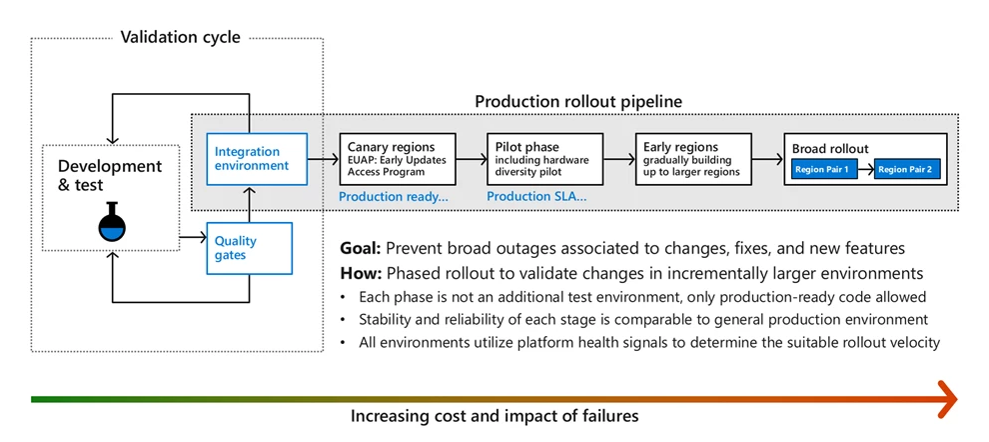
Mastering Maintenance – Strategies for seamless auto-updates on Azure SQL Managed Instance
Introduction
When it comes to managing your Azure SQL Managed Instances and ensuring their reliability and performance, understanding planned maintenance events is important. In this blog post, we will demystify how maintenance works, what to expect during the maintenance process, and some of the considerations and best practices associated with them.
Across Azure services, a unified process is followed to ensure that changes are carefully introduced and validated before reaching the production stage. This approach revolves around the following key principles:
Quality Assurance through Testing: Changes go through rigorous test and integration validations to ensure they meet Azure’s quality standards before deployment.
Gradual Deployment and Continuous Monitoring: Changes are rolled out in a gradual manner, allowing Azure to measure health signals continuously. This enables the detection of unexpected impacts that might not have surfaced during testing.
Avoiding Production Impact: The goal is to prevent change from causing problems in the broader production environment. Steps are taken to prevent problematic changes from reaching a wide audience.
To automate change deployment while adhering to the principles above, Azure follows the Safe Deployment Practice (SDP) framework. This applies to all Azure SQL Managed Instance logical upgrades (all that are SQL related). The SDP framework ensures that all code and configuration changes progress through specific stages, monitored by health metrics. Automated actions and alerts are triggered if any degradation is detected, ensuring timely responses to potential issues.
The deployment journey begins with developers modifying their code and testing it on their systems. The code then moves to staging environments, where interaction between different components is tested. Azure’s integration environment comes into play here, as it is dedicated to testing interactions between specific Azure services.
The subsequent stages include:
Canary Regions: Publicly referred to as “Early Updates Access Program” regions, these full-scale Azure regions host a diverse set of services, including first-party, third-party, and invited external customers. Canary regions undergo extensive end-to-end validations and scenario coverage at scale, aiming to replicate patterns found in public Azure regions.
Pilot Phase: After successful validation in canary regions, changes enter the pilot phase. This phase, while still relatively small in scale, introduces more diversity in hardware and configurations. It is especially vital for hardware-dependent services like core storage and compute infrastructure.
Broad Deployment: Upon positive outcomes from the pilot phase, changes are incrementally deployed to broader Azure regions. Respect for region pairing is maintained throughout this process. If any health signals arise, the deployment is paused for a thorough examination. Any changes that might introduce a regression are excluded from the payload before deployment proceeds.
The Role of Maintenance Windows
Azure maintenance windows are designated periods of time during which Microsoft performs routine maintenance tasks on its infrastructure. These tasks can include updates to the underlying infrastructure, software patches, or other improvements aimed at enhancing security, performance, or stability.
Azure’s maintenance windows are the key to orchestrating smooth updates and patches across its vast infrastructure. These windows are carefully designed time frames during which updates are applied to the regions where your instance is deployed. Once the code reaches the region where your instance is deployed, the maintenance windows ensure that the slots when these deployments occur are narrowed. By strategically narrowing down these slots, Azure aims to minimize potential disruptions caused by maintenance activities.
During maintenance windows, Azure services are fully online, but might experience transient faults such as brief network interruptions or temporary loss of connectivity to a database. However, these transient faults can be eliminated with proper retry logic in place at the application level. Retry logic is designed to handle these transient faults by automatically retrying failed operations.
Understanding Maintenance Window Options
Currently, Azure SQL Managed Instance offers three distinct maintenance window options, each tailored to different needs:
Default Window: This window spans from 5 PM to 8 AM of the next day, encompassing all days of the week. While it does not mean that every day within this range will see maintenance events, it signifies that these days are candidates for deployments.
Weekday Slot: Operating from Monday to Thursday, this window runs from 10 PM in the evening until 6 AM the next morning. The narrower time span allows for focused maintenance activities, while still ensuring your Azure SQL Managed Instances are online during most of the window.
Weekend Slot: Extending from Friday to Sunday, the weekend slot provides an extended period for maintenance activities. Like the other slots, instances remain operational during this window, with potential failovers having limited impact.
Note: Local time Zone is determined by the location of Azure region that hosts the resource and may observe daylight saving time in accordance with local time zone definition. It is not determined by the time zone configured on the managed instance.
Maintenance Process
Once the maintenance window selection is made and service configuration completed, planned maintenance will occur only during the window of your choice. As the window opens and if maintenance has been scheduled for the underlying services (Maintenance does not happen in every window) Azure’s deployment process begins. The virtual machines hosting the managed instances go through a rolling upgrade process where the process involves updating individual virtual machines one by one, rather than updating the entire system at once. If all the necessary Virtual machines or hosts are patched within the window, the event concludes without a hitch. However, if there are outstanding updates, the event might be extended to the next day or week, based on the maintenance window configuration.
The maintenance event may contain updates for hardware, firmware, operating system, satellite software components, or the SQL database engine. They are typically combined into a single batch to minimize the incidence of maintenance events. In the case of SQL Managed Instance, updates are combined in two batches, one focused on physical infrastructure, and another one focused on SQL engine and logical infrastructure.
Throughout the planned maintenance event, resources within your Azure SQL Managed instance environment remain accessible, ensuring minimal disruption to your services. This means that, for the most part, your database remains operational and responsive. Towards the end of the maintenance event, there is a brief reconfiguration period that occurs. During this time, some changes are applied to your database resources. However, this period is intentionally kept extremely short, typically lasting less than 8 seconds. The brevity of this reconfiguration minimizes the impact on your application’s availability.
If your application is actively engaged in a long-running process (for example – a long running query in a database) when the reconfiguration occurs, it may need to reestablish its connection to the database. This is akin to what happens in an on-premises scenario when a primary database fails over to a secondary one. Having robust retry logic in your application is crucial during planned maintenance events. This logic should be programmed to handle temporary connection interruptions gracefully. If a connection is lost, the application should automatically attempt to reconnect. A well-implemented retry mechanism ensures that your application can continue its operations seamlessly after a brief interruption.
Azure SQL Managed Instance failover for high availability refers to the process and mechanisms Azure employs to ensure that your SQL Managed Instances remain highly available, especially in the face of potential disruptions such as hardware or software failures, maintenance activities, or other unexpected events. Azure SQL Managed Instance automatically handles failover in the background. In the event of a failure, it automatically switches to a standby replica to ensure minimal disruption to services.
Failovers play a crucial role in maintaining service availability during maintenance windows. If a host or VM with an Azure SQL managed instance primary replica is being patched, a failover can swiftly transfer operations to ensure continuity. These failovers typically occur one to two times during a maintenance slot, lasting around 8 seconds.
For Azure SQL Managed Instances in the business-critical tier, failovers are even faster due to the optimized setup of Always On Availability Groups and local storage.
If one is implementing disaster recovery through the configuration of auto-failover groups in Azure SQL Managed instance, we recommend that you replicate workloads across regional pairs to benefit from Azure’s isolation and availability policies. Also, failover groups in paired regions have better performance compared to unpaired regions. Azure paired regions are guaranteed not to be deployed to at the same time. However, it is not possible to predict which region will be upgraded first, so the order of deployment is not guaranteed. Sometimes, your geo-primary instance will be upgraded first, and sometimes it will be the geo-secondary.
In situations where your Azure SQL managed instance has auto-failover groups, and the groups are not aligned with the Azure region pairing, you should select different maintenance window schedules for your primary and secondary database. For example, you can select Weekday maintenance window for your geo-secondary database and Weekend maintenance window for your geo-primary database.
Although rare, failures or interruptions during a maintenance event can occur. In case of a failure, changes are rolled back, and the maintenance will be rescheduled to another time.
Considerations
Azure SQL Managed Instance consists of service components hosted on a dedicated set of isolated virtual machines that run inside the customer’s virtual network subnet. These virtual machines form “virtual machine group” that can host multiple managed instances. All instances hosted in a “virtual machine group” share the same maintenance window. Specifying another maintenance window for managed instance during its creation or afterwards means that it must be placed in “virtual machine group” with corresponding maintenance window. If there is no such “virtual machine group” in the subnet, a new one must be created first to accommodate the instance. Accommodating additional instances in the existing “virtual machine group” may require a resize of the “virtual machine group”.
One cannot restore a database when the above change is going on.
Expected duration of configuring maintenance window on managed instance can be calculated using estimated duration of instance management operations.
Each new virtual machine group in a subnet requires additional IP addresses according to the virtual cluster IP address allocation.
Changing a maintenance window for an existing managed instance also requires temporary additional IP capacity, similar to when scaling the number of vCores for the respective service tier.Configuring and changing maintenance window causes change of the IP address of the instance, within the IP address range of the subnet.
Advanced Notifications
You can opt in to receive notification 24 hours prior to the maintenance event, immediately before maintenance starts, and when the maintenance window is completed. The Resource health center can be checked for more information. To receive emails, advance notifications must be configured. For more information, see Advance notifications.
As of this writing, advanced notifications for maintenance windows are in public preview for Azure SQL Managed Instance.
Best practices for resiliency during maintenance operations.
Implement retry logic in your applications for all transient errors common to the cloud environment. See this sample source code for the connection retry logic.
Use the latest drivers to connect to SQL Managed Instance. Newer drivers have a better implementation of transient error handling.
Test your application for resiliency prior to the maintenance events using User Initiated failover functionality for SQL Managed Instance.
From a networking perspective, choose the redirect connectivity mode over proxy. With Redirect, the client directly connects to the node hosting the database and does not need to connect to the gateway. This makes the SQL managed instance resilient on gateway maintenance for already established connections.
Reference: Connection types – Azure SQL Managed Instance | Microsoft Learn.
Conclusion
By understanding what to expect during a planned maintenance event and having appropriate measures in place, such as retry logic, error handling and selecting the proper connectivity mode you can help ensure a smooth transition through these events and maintain a high level of service availability for your Azure SQL Managed Instance.
Additional References
Maintenance Window – Azure SQL Database & Azure SQL Managed Instance | Microsoft Learn
Configure maintenance window – Azure SQL Database | Microsoft Learn
Maintenance Window FAQ – Azure SQL | Microsoft Learn
Video: Understanding Maintenance in Azure SQL by Rie Merritt at SQL Bits 2023
Video: High availability for Azure SQL Managed Instance with a DEMO
Microsoft Tech Community – Latest Blogs –Read More

Infra in Azure for Developers – The How (Part 1)
We’ve looked at the why and what of infra for developers so now it’s time to put it into action with the how. What separates this from a more generic tutorial on Azure infra? This is not meant to cover the whole gamut of Azure services – it is intended to solve an isolated part of the puzzle; namely the deployment of developer output. You can certainly build on this or re-use for other purposes, but this isn’t about creating a complete platform as such.
Disclaimer: While I strive to follow best practices the focus is on the concepts and not a battle hardened solution. This is not production grade.
Hammering out the infrastructure
I noticed during production that this would become a rather lengthy post, so I have split things into two parts with this laying the foundation with regards to the infrastructure. (I feel we cover quite a lot here as well so feel free to top up your coffee cup first.)
We need a problem to solve here – I believe the eShop sample is a good example of a reference application. There are actually multiple eShop versions:
eShopOnWeb – https://github.com/dotnet-architecture/eShopOnWeb This is a monolithic implementation.
“New” eShop – https://github.com/dotnet/eShop A microservices-based implementation using containers.
eShopOnAzure – https://github.com/Azure-Samples/eShopOnAzure The microservice-based implementation using Azure services.
Both monolith and microservices are valid options for demonstrating how .NET works, but we will base ourselves on the microservices implementation here.
The code for this article can be found here: https://github.com/ahelland/infra-for-devs
It could make sense to base ourselves on the Azure version, but that one seems to not quite be ready yet as I’m seeing various issues trying to build it so for now we will use the plain version.
I cloned it to my disk and tried spinning it up using Aspire. The web app works, but the interesting bit right now is the Aspire Dashboard:
Aspire dashboard
We can see that there are three external components to the code (in line with the architecture diagram) packaged in containers and the different microservices running un-containerized. For running in Azure it would probably make sense to put everything in containers. There is also a dependency on Duende IdentityServer for login functionality, but that is part of the code so it doesn’t require any extras as such.
Container hosting
This leads to the first infrastructure related design question – which service should be used for hosting the containers? As a developer you have to make architectural choices about your code; which logging framework to use, which testing strategy, etc. The same applies for infrastructure.
“But I don’t know about infra”, or “I don’t what to figure out those things”? If that is what you’re thinking you are bringing up a good point. My point in writing these posts is de-mystifying the infrastructure parts of bringing a solution to Azure, but as I said in the first post this is not about making developers do everything.
In our case we will go for Azure Container Apps because I believe that is a good abstraction on top of Kubernetes. Azure Kubernetes Service is also good, but unless you have a need for digging into Kubernetes details and customize accordingly Container Apps is more developer friendly.
I wanted to include a list of design goals, but it felt a little contrived. Sure, I want to follow best practices from Microsoft where possible; we’ll tackle that as we go along. An extra challenge we will throw in is to see if we can make eShop run on a private network in Azure. (In the enterprise space many will prefer that.)
Tooling
Before we dive into the implementation a few notes on the tooling. Visual Studio 2022 supports Bicep, but in my own experience it’s a better experience to use Visual Studio Code for IaC.
You should also install the Azure CLI and PowerShell. While techically not required (for Bicep in general or this post), I also find it very useful to have WSL installed as some things are just plain easier to do on Linux 🙂
And throw in the Bicep extension in VS Code as well. I also highly recommend the Polyglot Notebooks extension – that serves as my tool for deploying Bicep locally.
After installing the Polyglot notebooks extension it can be invoked with Ctrl+Shift+P (default on Windows) to create a new notebook:
I’ve found the .dib format most useful for this purpose:
It’s just the defaults – it’s flexible afterwards.
I chose to save it directly under /infra as playbook.dib. And now you have the option to execute code inline and explain with Markdown along the way:
Folder structure
For now we just have infra in our repo (code to be added later) so we put the Bicep in a folder called /infra with sub-folders for modules and the levels.
I’ve seen various setups with regards to where one puts infrastructure-as-code (regardless of whether it’s Bicep, Terraform or something else). Should it be in the same repo as the application code or in a separate repo? I have taken the decision to co-locate it here to reduce complexity, but I tend to prefer at least the modules being in a separate repo. (The approach here is very solution centric so if you go down the route of building a platform you probably need to structure things differently.) But of course the whole monorepo vs multi-repo is a discussion of its own in which IaC is just another piece of the puzzle.
CI/CD
I think we can all agree that the age of compiling code and putting in on a USB stick for someone else to copy on to the server is over and I believe you should build and deploy through Azure DevOps or GitHub. In this post I will not be using those services for two reasons:
Running things through a pipeline adds some complexity since you have to type up some yaml, possibly build some private agents, fix permissions and so on. Maybe I’ll do a follow-up post on that – haven’t decided.
As a .NET developer your inner loop is pressing F5. You don’t create a pull request for every piece of code you write before verifying you are able to compile locally. While the ARM APIs enable a basic level of verification to happen locally attempting to deploy to Azure is basically the IaC developer’s “F5 experience”. (To a subscription where you are allowed to mess things up.)
Azure resources
Here is the component diagram of eShop: https://github.com/dotnet/eShop/blob/main/img/eshop_architecture.png
So, what will we need to create? A few things come to mind:
Virtual network
Private DNS Zone
Azure Container App Environment
Azure Container Registry
Container Apps
If I were to create an app from scratch I would probably have used different components – replacing RabbitMQ with Azure Service Bus is an obvious choice. But the choices made while coding eShop is not our concern for now.
Bicep modules
A thing that might be a bit frustrating at first using Bicep is how you’re forced to use modules. In C# you can choose if you want to use interfaces, use dependency injection, put things in a shared dll and so on – you don’t want to go down the route of “Hello World Enterprise Edition” for all your apps. Due to how scopes work with ARM you don’t get the same flexibility with Bicep. Once you get used to it it’s fairly pain-free though and I think it provides a clear abstraction between definitions and instantiations. (Side note: Terraform has solved this by creating additional abstractions on top of ARM that takes care of this when you use the AzureRM provider, but underneath it’s the same.)
Personally I use the Bicep Registry Module tool which is an additional installation:
https://www.nuget.org/packages/Azure.Bicep.RegistryModuleTool
So, for something like a container app environment module you would do the following:
Create a subfolder containers for the namespace.
Create a subfolder container-environment. (You can choose the name.)
Change to the subfolder and run brm generate to scaffold the files.
Fill in metadata.
Write the actual module code.
Create main.test.bicep (in the modules test subfolder).
Run brm validate to check you have missed a description or something.
I usually apply a PSRule step at the end as well, but we can get back to that later. (PSRule checks your Bicep against the Azure baselines to make suggestions on improvements.)
How to create a module? Let’s use the private DNS Zone as an example. (Mostly because it’s not too code heavy.)
You can create it through click-ops in the Azure Portal and import to VS Code afterwards with the Insert Resource action:
That will create Bicep for that specific instance so you need to make it generic yourself.
Once you get things more into your fingers you can start with the reference docs and work it out manually:
https://learn.microsoft.com/en-us/azure/templates/
Or some combination of the two as it’s not always that easy to figure out the reference docs either.
The docs tells us that the Private DNS Zone is part of the Network provider so while in the /infra/modules/network folder we create a sub-folder and let brm scaffold the files for us:
Which will give you the following files:
main.json will be generated by the tooling so ignore. README.md will also be generated though you can add to it manually if you will.
version.json needs a version number added manually like this:
{
“$schema”: “https://aka.ms/bicep-registry-module-version-file-schema#”,
“version”: “0.1”,
“pathFilters”: [
“./main.json”
]
}
main.bicep is the important part and you need to fill in some metadata first as a minimum:
metadata name = ‘Private DNS Zone’
metadata description = ‘A module for generating an empty Private DNS Zone.’
metadata owner = ‘ahelland’
And then you add some more Bicep code:
@description(‘Tags retrieved from parameter file.’)
param resourceTags object = {}
@description(‘The name of the DNS zone to be created. Must have at least 2 segments, e.g. hostname.org’)
param zoneName string
@description(‘Enable auto-registration for virtual network.’)
param registrationEnabled bool
@description(‘The name of vnet to connect the zone to (for naming of link). Null if registrationEnabled is false.’)
param vnetName string?
@description(‘Vnet to link up with. Null if registrationEnabled is false.’)
param vnetId string?
resource zone ‘Microsoft.Network/privateDnsZones@2020-06-01’ = {
name: zoneName
location: ‘global’
tags: resourceTags
resource vnet ‘virtualNetworkLinks@2020-06-01’ = if (!empty(vnetName)) {
name: ‘${vnetName}-link’
location: ‘global’
properties: {
registrationEnabled: registrationEnabled
virtualNetwork: {
id: vnetId
}
}
}
}
You should be able to figure out most of these things I assume.
For static code validation purposes you also need to add code to main.test.bicep:
targetScope = ‘subscription’
param location string = ‘norwayeast’
param resourceTags object = {
value: {
IaC: ‘Bicep’
Environment: ‘Test’
}
}
resource rg_dns ‘Microsoft.Resources/resourceGroups@2022-09-01’ = {
name: ‘contoso-dns’
location: location
tags: resourceTags
}
module dnsZone ‘../main.bicep’ = {
scope: rg_dns
name: ‘dns’
params: {
resourceTags: resourceTags
registrationEnabled: false
vnetId: ”
vnetName: ”
zoneName: ‘contoso.com’
}
}
Note that I am not supplying properties for the virtual network here. I could of course supply dummy values, but this module in isolation does not provide a virtual network. It is also a valid use case to not enable automatic registration (They are also nullable params in the main.bicep file so that’s why I’m not getting any complaints.)
Now your module is done so it can be verifed with the brm validate command. As you will see you do need to run brm generate once more to regenerate files (it will also call out things like you forgetting to decorate params with descriptions):
Do I have to write all these modules from scratch? No, you don’t actually have to do that. That is, as so many things in life – it depends. Microsoft has several options on offer to reduce your module making job:
Bicep Registry Modules: https://github.com/Azure/bicep-registry-modules
CARML: https://github.com/Azure/ResourceModules
Azure Verified Modules: https://azure.github.io/Azure-Verified-Modules/
Yeah, that’s not confusing at all 🙂 The current line of thinking is that they will converge into the Verified Modules initiative, but we’re not quite there yet. In short – there might be a ready-made module for you, and there might not.
Another nifty thing about modules is that you can push them to a container registry and consume them like independent artifacts. Which enables use cases like Microsoft offering said Bicep modules and you sharing internally between projects. This brings up the question – how can I consume modules when I use Bicep to create the registry? You clearly cannot consume from a registry if you haven’t created it yet. You’re not forced to do so either; you can refer directly through the file system. In a more complex setup you might want to have a separate registry for Bicep modules that are bootstrapped at an earlier stage than deploying the apps infra.
Bicep modules can be published (to the registry) like this:
$target=”br:contoso.azurecr.io/bicep/modules/private-dns-zone”
az bicep publish –file main.bicep –target $target –verbose
Pro-tip: this doesn’t scale so use the tasks feature in VS Code.
Create a subfolder called tasks under /infra (you can choose a different name)
Create a PowerShell script – I called mine publish_modules.ps1 (replace the value of $registryName):
#Loop through the modules directory, retrieve all modules, extract version number and publish.
$rootList = (Get-ChildItem -Path modules -Recurse -Directory -Depth 0 | Select-Object Name)
foreach ($subList in $rootList)
{
$namespace=$subList.name
foreach ($modules in $(Get-ChildItem -Path ./modules/$namespace -Recurse -Directory -Depth 0 | Select-Object Name))
{
$module=$modules.Name
$version=(Get-Content ./modules/$namespace/$module/version.json -Raw | ConvertFrom-Json).version
$registryName=”contosoacr”
$target=”br:” + $registryName + “.azurecr.io/bicep/modules/” + $namespace + “/” + $module + “:v” + $version
az bicep publish –file ./modules/$namespace/$module/main.bicep –target $target –verbose
}
}
Create .vscode as a subfolder under /infra and create a tasks.json with the following contents:
{
“version”: “2.0.0”,
“tasks”: [
{
“label”: “Publish modules to container registry”,
“type”: “shell”,
“command”: “./tasks/publish_modules.ps1”,
“presentation”: {
“reveal”: “always”,
“panel”: “dedicated”
}
}
]
}
If you invoke Ctrl-Shift-P now you will have a new task at your disposal:
Since we haven’t created the registry yet it is not going to work yet though.
Infrastructure levels
I mentioned previously that the layered infra approach from the Cloud Adoption Framework makes sense so we will follow that pattern and deploy accordingly. Mind you – it probably makes sense to explain my numbering here. Sometimes you have a level 0 – that’s where you do bootstrapping that isn’t part of the actual deployment of resources, but it could be you need to do some prepwork like registering resource providers to enable the rest to work.
Level 1 is where you would do governance things like setting up a log analytics workspace for the infra resources. Maybe a Key Vault for encryption keys you need later. We will not use a level 1 and skip straight to Level-2.
Level 2
This is where we start creating stuff. Since we want things to run on a private network we need to create a network (with subnets) and a private DNS zone. Some extra notes on these are probably helpful to set the context.
Take care of where you deploy your vnet as it needs to align with the services you need. If you deploy your network to North Europe but the services you want are only available in East US that’s not going to work. If you like trying out services that are in preview it is very common that these are not offered in all regions. (You can create multiple networks in different regions and connect them, but that is far out of scope for this blog post.)
Private DNS zones takes care of name resolution, but as the name implies it is private. You can create microsoft.com and as it is not exposed to the internet it’s not a problem. Until you sit on your developer laptop and have no means of connecting to resolve those names. The easy fix in our context is to create Azure Dev Boxes attached to the vnet. The “proper” fix is to create a connection between your on-premises network and Azure (using S2S VPN or ExpressRoute) and set up a private DNS resolver. For that matter you could also set up P2S VPN and have each developer tunneling their laptop into Azure. Once again – slightly out of scope here.
And by now you’re probably thinking your head hurts. I know. Isn’t there an easy way out? Well, yes, avoid using private networks and follow the defaults that give you public access on every resource. Clearly not the response you will get from the network team though if you have to run things by them 🙂
Our level-2 ends up being fairly stripped down:
targetScope = ‘subscription’
@description(‘Azure region to deploy resources into.’)
param location string
@description(‘Tags retrieved from parameter file.’)
param resourceTags object = {}
resource rg_vnet ‘Microsoft.Resources/resourceGroups@2021-04-01’ = {
name: ‘rg-eshop-vnet’
location: location
tags: resourceTags
}
resource rg_dns ‘Microsoft.Resources/resourceGroups@2021-04-01’ = {
name: ‘rg-eshop-dns’
location: location
tags: resourceTags
}
param vnetName string = ‘eshop-vnet-weu’
module vnet ‘br/public:network/virtual-network:1.1.3’ = {
scope: rg_vnet
name: ‘eshop-vnet-weu’
params: {
name: vnetName
location: location
addressPrefixes: [
‘10.1.0.0/16’
]
subnets: [
{
name: ‘snet-devbox-01’
addressPrefix: ‘10.1.1.0/24’
privateEndpointNetworkPolicies: ‘Enabled’
}
{
name: ‘snet-cae-01’
addressPrefix: ‘10.1.2.0/24’
privateEndpointNetworkPolicies: ‘Enabled’
delegations: [
{
name: ‘Microsoft.App.environments’
properties: {
serviceName: ‘Microsoft.App/environments’
}
type: ‘Microsoft.Network/virtualNetworks/subnets/delegations’
}
]
}
{
name: ‘snet-pe-01’
addressPrefix: ‘10.1.3.0/24’
privateEndpointNetworkPolicies: ‘Enabled’
}
]
}
}
//We import the vnet just created to be able to read the properties
resource vnet_import ‘Microsoft.Network/virtualNetworks@2023-06-01’ existing = {
scope: rg_vnet
name: vnetName
}
//Private endpoint DNS
module dnsZoneACR ‘../modules/network/private-dns-zone/main.bicep’ = {
scope: rg_dns
name: ‘eshop-private-dns-acr’
params: {
resourceTags: resourceTags
registrationEnabled: false
vnetId: vnet_import.id
vnetName: vnetName
zoneName: ‘privatelink.azurecr.io’
}
}
The network module is from the Microsoft public registry because the needs here do not require a custom module.
And here’s where the polyglot notebooks come in handy. I create small blocks of code like this which can be run with the Play icon in the upper left corner:
# A what-if to point out errors not caught by the linter
#az deployment sub what-if –location westeurope –name level-2 –template-file .level-2main.bicep –parameters .level-2main.bicepparam
# A stand-alone deployment
# az deployment sub create –location westeurope –name DevCenterStack –template-file main.bicep –parameters .main.bicepparam
# A deployment stack
az stack sub create –name eshop-level-2 –location westeurope –template-file .level-2main.bicep –parameters .level-2main.bicepparam –deny-settings-mode none
We haven’t really touched upon the functionality of Deployment Stacks, but I use it here as a logical collection of everything that goes into a level.
Since this is a private virtual network, and I’m not able to provide a working configuration for a VPN specific to your needs I’ve also included an option for deploying Dev Boxes to connected to this vnet. The details of Dev Box was covered in my previous post if you want to know more about that:
Level 3
A lot of the good things happen here. This is where we deploy our container environment and our container registry. You might think this is where you deploy the apps as well, but we will have them on the subsequent level. The Azure Portal experience is a bit misleading here – if you try to create a container environment you must create an app at the same time. However, if you work from IaC this is not a requirement. If you try to set up deployment of more than one container app you will appreciate splitting up the environment instantiation from the apps deployment.
Networking creeps in here even if it belongs to the previous level. The container registry needs private endpoints so they are created here, and attached to the dedicated subnet we have created. A more interesting bit is that we need to create a private DNS zone for the container environment. The environment gets a Microsoft-generated name so we can’t pre-create this. We also choose to put it in the resource group for the environment rather than our dedicated DNS resource group. Remember – resource groups are about life cycle. This DNS zone only has value when the container environment exists so that’s where it belongs. This also highlights that the levels are general guidelines not strict rules.
Think about dependency hierarchies in code. Having class A depend on class B works. But if class B depends on class C that might introduce an indirect dependency from class A to class C and those can be tricky to figure out when things break. Work through the mental model of your resources in Azure the same way.
Our level-3 ends up like this:
targetScope = ‘subscription’
@description(‘Azure region to deploy resources into.’)
param location string
@description(‘Tags retrieved from parameter file.’)
param resourceTags object = {}
resource rg_vnet ‘Microsoft.Resources/resourceGroups@2021-04-01’ existing = {
name: ‘rg-eshop-vnet’
}
resource rg_dns ‘Microsoft.Resources/resourceGroups@2021-04-01’ existing = {
name: ‘rg-eshop-dns’
}
resource rg_cae ‘Microsoft.Resources/resourceGroups@2021-04-01’ = {
name: ‘rg-eshop-cae’
location: location
tags: resourceTags
}
param vnetName string = ‘eshop-vnet-weu’
resource vnet ‘Microsoft.Network/virtualNetworks@2023-06-01’ existing = {
scope: rg_vnet
name: vnetName
}
resource rg_acr ‘Microsoft.Resources/resourceGroups@2021-04-01’ = {
name: ‘rg-eshop-acr’
location: location
tags: resourceTags
}
param acrName string = ‘acr${uniqueString(‘eshop-acr’)}’
//Private Endpoints require Premium SKU
param acrSku string = ‘Premium’
param acrManagedIdentity string = ‘SystemAssigned’
module containerRegistry ‘../modules/containers/container-registry/main.bicep’ = {
scope: rg_acr
name: acrName
params: {
resourceTags: resourceTags
acrName: acrName
acrSku: acrSku
adminUserEnabled: false
anonymousPullEnabled: false
location: location
managedIdentity: acrManagedIdentity
publicNetworkAccess: ‘Disabled’
}
}
//Private endpoints (two required for ACR)
module peAcr ‘acr-pe-endpoints.bicep’ = {
scope: rg_acr
name: ‘pe-acr’
params: {
resourceTags: resourceTags
location: location
peName: ‘pe-acr’
serviceConnectionGroupIds: ‘registry’
serviceConnectionId: containerRegistry.outputs.id
snetId: ‘${vnet.id}/subnets/snet-pe-01’
}
}
module acr_dns_pe_0 ‘../modules/network/private-dns-record-a/main.bicep’ = {
scope: rg_dns
name: ‘dns-a-acr-region’
params: {
ipAddress: peAcr.outputs.ip_0
recordName: ‘${containerRegistry.outputs.acrName}.${location}.data’
zone: ‘privatelink.azurecr.io’
}
}
module acr_dns_pe_1 ‘../modules/network/private-dns-record-a/main.bicep’ = {
scope: rg_dns
name: ‘dns-a-acr-root’
params: {
ipAddress: peAcr.outputs.ip_1
recordName: containerRegistry.outputs.acrName
zone: ‘privatelink.azurecr.io’
}
}
module containerenvironment ‘../modules/containers/container-environment/main.bicep’ = {
scope: rg_cae
name: ‘eshop-cae-01’
params: {
location: location
environmentName: ‘eshop-cae-01’
snetId: ‘${vnet.id}/subnets/snet-cae-01’
}
}
module dnsZone ‘../modules/network/private-dns-zone/main.bicep’ = {
scope: rg_cae
name: ‘${containerenvironment.name}-dns’
params: {
resourceTags: resourceTags
registrationEnabled: false
zoneName: containerenvironment.outputs.defaultDomain
vnetName: ‘cae’
vnetId: vnet.id
}
}
module userMiCAE ‘../modules/identity/user-managed-identity/main.bicep’ = {
scope: rg_cae
name: ‘eshop-cae-user-mi’
params: {
location: location
miname: ‘eshop-cae-user-mi’
}
}
module acrRole ‘../modules/identity/role-assignment-rg/main.bicep’ = {
scope: rg_acr
name: ‘eshop-cae-mi-acr-role’
params: {
principalId: userMiCAE.outputs.managedIdentityPrincipal
principalType: ‘ServicePrincipal’
roleName: ‘AcrPull’
}
}
A few things of note here:
We need properties from the virtual network we created. We solve this by importing it with the existing keyword and referencing it’s properties.
The private networking feature of the container registry requires the Premium SKU. (Whenever a feature is “enterprisey” don’t be surprised if it costs more.)
While the private endpoint concept works across all resources the details can differ. For ACR we require two endpoints. For something like Storage you need endpoints for all services – one for blob, one for tables, etc. We create a module specifically for ACR in this case.
The DNS zone has a dependency on the Container Environment being created first so we can retrieve the domain name, but Bicep figures out this based on our cross-resource references since we work in the same scope.
We create a user-assigned identiity to be able to pull images from ACR when creating the container apps. A container app can have a system-assigned identity as well (great for granular access control), but it can’t be used for pulling the image as that would create a chicken and egg problem since the identity doesn’t exist until the app has been created. (Workarounds available, but not recommended.)
This takes care of the classic infra stuff if you will – feels more like coding, right? It may very well be that this is handled by your DevOps engineer should you have one, or your platform team for that matter. At this lab scale it should be manageable for a dev as well; either way – it’s useful background information to broaden your horizon.
It also closes off part one of this walkthrough. The rest of the code can be found here: https://github.com/ahelland/infra-for-devs
We still have the actual services to deploy, and that will be covered in part two of this walkthrough.
Microsoft Tech Community – Latest Blogs –Read More

Feature Deep Dive: Open in App
OneDrive is excited to launch the Open in App feature, a game-changer for those who prefer working directly in native applications.
Until now, only Word, PowerPoint, and Excel files could be opened in their native desktop applications; other file types like PDFs, JPEGs, or MP4s would open in a preview mode where you would be able to view but not edit the file. We’ve heard your feedback around wanting a more seamless workflow, directly accessing and editing all of your files in their dedicated apps, not just Word, PowerPoint, and Excel. Open in App makes this possible.
Now, while working with OneDrive or SharePoint in a browser, or the latest version of Teams, you can open files directly in their native applications. You can edit as needed, and then be assured that your changes will be saved right back to the cloud, maintaining a smooth and efficient workflow.
Effortlessly open and edit files in their native apps
Using the new Open in App experience is simple. Imagine you’re in your favorite browser, using your Microsoft work or school account. In the My files view in OneDrive or a SharePoint document library, right-click on a file, then select Open > Open in app. The file will open in its native app, directly from your browser. You get the benefit of full functionality, allowing you to access the complete set of features and tools that the application offers.
Seamlessly open your files in a desktop app by selecting Open in app in the My files view in OneDrive for Web.
Open SharePoint files in their desktop apps by selecting Open in app in SharePoint.
Using Open in App in Microsoft Teams
This seamless experience isn’t just for your browser. It also works with the latest version of Teams. To open your OneDrive files in their native apps from Teams, navigate to the My files view, right-click on a file and select Open > Open in app.
Open your files in their native desktop apps from the My files view in the Teams client by selecting Open in app.
To open your teams’ shared files in their native apps from Teams, navigate to a channel, select the Files pivot, right-click on a file and select Open > Open in app.
Easily collaborate with your team by opening and editing shared files in their native desktop apps by selecting Open in app in Teams channels.
Choosing default apps
If there is a default app available to open the file, then the Open in app option automatically chooses that app to open your file. When a default app is not configured, the system will ask you to select a default app, giving you the flexibility to configure specific default apps for different file types. Once opened, you can make and save changes to a file in the desktop app, and any changes you save will sync back to OneDrive or SharePoint.
You can easily configure a default app for different file types
You can easily configure a default app for different file types.
Availability and requirements
Open in app is currently rolling out to work and school accounts on Windows and macOS devices that have the OneDrive sync client installed. If the sync client is installed but not running, selecting Open in app will start the client. You will also need to have the desired native desktop applications installed on your PC or Mac. This feature is not yet available for personal accounts or on other operating systems. Learn more.
We hope you find Open in app useful when working with your files in OneDrive, SharePoint, and Teams! If you have questions or comments, please leave them below. Additionally, commercial customers are welcome to join OneDrive Customer Office Hours, a monthly Microsoft Teams meeting where our product team will answer your questions, demo new features, and get your feedback. To get on the meeting invite list, just sign up for OneDrive Customer Office Hours. You can also download the OneDrive quick start guide or sign up for the OneDrive newsletter.
About the author
Kayla Ngan is a Principal Product Manager on the OneDrive Sync team. She joined the team in November 2020. In her free time, she enjoys being outdoors, traveling, and eating sushi.
Microsoft Tech Community – Latest Blogs –Read More
MFA App ID deprecation in Exchange Online
We wanted to inform you of an important update regarding MFA App ID (Microsoft Exchange Online Remote PowerShell App ID) used in Exchange Online. The MFA App ID (a0c73c16-a7e3-4564-9a95-2bdf47383716) will be deprecated by the end of March 2024. After that date, the App ID will no longer be operational.
What is the MFA app Id?
The MFA App ID is an Azure-based identifier used for authentication purposes to access Exchange Online resources. This App ID was specifically designed for the now-deprecated Exchange Online PowerShell v1 module also called as MFA v1 module, which has been replaced by the more robust Exchange Online v3 module. As the MFA module is no longer supported, and other use of this App ID was never officially documented and recommended by Microsoft, we have decided to proceed with its deprecation. We already made this deprecation announcement in Partner Center during February and August 2023.
Who is impacted by this change?
There are three ways in which you could possibly be impacted by this deprecation:
When you connect to Exchange Online using the Exchange Online PowerShell V3 module’s Connect-ExchangeOnline cmdlet, and you are using the -AccessToken parameter and passing the MFA App ID mentioned above.
You have written an in-house (home grown) app that still uses this App ID. Please check your source code for the presence of this App ID.
If you use a 3rd party app that uses this App ID, your tenant might get a Message Center post about this change. Please check with your 3rd party vendors if they used this App ID.
What you should do.
Although Microsoft never officially recommended the use of MFA App Id, we understand that over the years, some of our partners and customers may have taken dependency on this App ID. If you are currently using the MFA App ID, we urge you to transition away from it as soon as possible to avoid any service disruptions.
To replace the MFA App ID in case you use it, we recommend you start using the v3 PowerShell module without using MFA app id as an access token or create a new Application through the Azure portal, ensuring it has the necessary permissions for your required operations and make use of this newly created app ID to login to Exchange Online. For detailed information about Application Id creation and consumption you can refer to: App-only authentication in Exchange Online PowerShell and Security & Compliance PowerShell | Microsoft Learn.
Have additional concerns?
In case you have any concerns regarding the MFA app ID deprecation, you can reach out to us at MFAAppIDDeprecation(AT)service.microsoft.com.
Exchange Online Manageability Team
Microsoft Tech Community – Latest Blogs –Read More
MFA App ID deprecation in Exchange Online
We wanted to inform you of an important update regarding MFA App ID (Microsoft Exchange Online Remote PowerShell App ID) used in Exchange Online. The MFA App ID (a0c73c16-a7e3-4564-9a95-2bdf47383716) will be deprecated by the end of March 2024. After that date, the App ID will no longer be operational.
What is the MFA app Id?
e MFA App ID is an Azure-based identifier used for authentication purposes to access Exchange Online resources. This App ID was specifically designed for the now-deprecated Exchange Online PowerShell v1 module also called as MFA v1 module, which has been replaced by the more robust Exchange Online v3 module. As the MFA module is no longer supported, and other use of this App ID was never officially documented and recommended by Microsoft, we have decided to proceed with its deprecation. We already made this deprecation announcement in Partner Center during February and August 2023.
Who is impacted by this change?
There are three ways in which you could possibly be impacted by this deprecation:
When you connect to Exchange Online using the Exchange Online PowerShell V3 module’s Connect-ExchangeOnline cmdlet, and you are using the -AccessToken parameter and passing the MFA App ID mentioned above.
You have written an in-house (home grown) app that still uses this App ID. Please check your source code for the presence of this App ID.
If you use a 3rd party app that uses this App ID, your tenant might get a Message Center post about this change. Please check with your 3rd party vendors if they used this App ID.
What you should do.
Although Microsoft never officially recommended the use of MFA App Id, we understand that over the years, some of our partners and customers may have taken dependency on this App ID. If you are currently using the MFA App ID, we urge you to transition away from it as soon as possible to avoid any service disruptions.
To replace the MFA App ID in case you use it, we recommend you start using the v3 PowerShell module without using MFA app id as an access token or create a new Application through the Azure portal, ensuring it has the necessary permissions for your required operations and make use of this newly created app ID to login to Exchange Online. For detailed information about Application Id creation and consumption you can refer to: App-only authentication in Exchange Online PowerShell and Security & Compliance PowerShell | Microsoft Learn.
Have additional concerns?
In case you have any concerns regarding the MFA app ID deprecation, you can reach out to us at MFAAppIDDeprecation(AT)service.microsoft.com.
Exchange Online Manageability Team
Microsoft Tech Community – Latest Blogs –Read More
Access Releases 9 Issue Fixes in Version 2312 (Released January 4th, 2024)
Our newest round of Access bug fixes was released on January 4th, 2024. In this blog post, we highlight some of the fixed issues that our Access engineers released in the current monthly channel.
If you see a bug that impacts you, and if you are on the current monthly channel Version 2312, you should have these fixes. Make sure you are on Access Build # 16.0.17126.20126 or greater.
Bug Name
Issue Fixed
No list of font sizes when Aptos font is selected
Aptos is the default font for controls in a new database using the recently updated ‘Office Theme,’ but the font size drop down was not displaying a list of font sizes (although you could manually type in a font size).
When a query was open in datasheet or design view, the context menu command to open in SQL View in the navigation pane would not switch the open query to SQL View
This command on the context menu was recently added to allow opening a query directly into SQL view. However, to be consistent with other commands, it now switches the mode of a query that is already open to SQL view.
#Error when using DateDiff with one Date/Time column and one Date/Time Extended column
The DateDiff function was working correctly if both arguments were of type Date/Time, or both arguments were of type Date/Time Extended but would fail to evaluate with one argument of each type.
The updated linked table manager no longer shows the name of the DSN used for a linked table
The old, linked table manager displayed this information. The new linked table manager now also displays it.
Access may terminate unexpectedly when running a macro after editing it
In some cases, after adding/removing/moving macro actions in the macro designer, then attempting to run the macro, Access would terminate unexpectedly. This no longer occurs.
F1 does not display the correct help page when used on some properties/methods of the Field2 object in the VBA IDE
F1 now directs to the appropriate help page for the following properties/methods:
CreateProperty, Expression, IsComplex, Name, Required, SourceTable, Type, ValidationRule, ValidationText, and Value.
Some valid values for the DBEngine.SetOption method have no defined constant
The following constants were added:
dbPagesLockedToTableLock, dbPasswordEncryptionProvider, dbPasswordEncryptionAlgorithm, dbPasswordEncryptionKeyLength
Subform control does not support LabelName property
The LabelName property was shown in the property sheet for every other control that supported child labels and is now present for subform controls as well.
Auto expand in combo boxes doesn’t work for list items >100 index
In some cases, autocomplete did not work for items in a dropdown list when there were more than 100 items in the list. This issue has been resolved.
Please continue to let us know if this is helpful and share any feedback you have.
Microsoft Tech Community – Latest Blogs –Read More
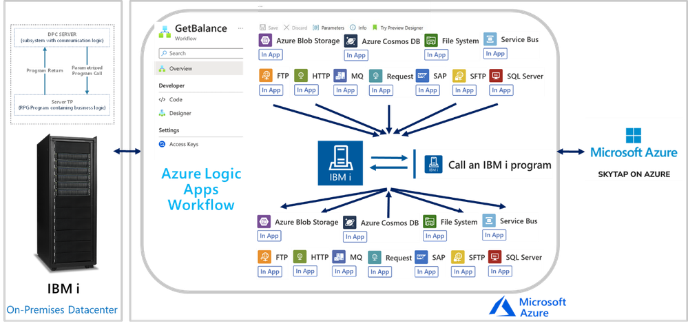
Logic Apps Mission Critical Series: “We Speak: IBM i: COBOL and RPG Applications”
In this session, we continue with the “We Speak”, Mission Critical Series with an episode on how Azure Logic Apps can unlock scenarios where is required to integrate with IBM i (i Series or former AS/400) Applications.
The IBM i In-App Connector
The IBM i In-App connector enables connections between Logic App workflows to IBM i Applications running on IBM Power Systems.
Background:
More than 50 years ago, IBM released the first midrange systems. IBM advertised them as “Small in size, small in price and Big in performance. It is a system for now and for the future”. Over the years, the midranges evolved and became pervasive in medium size businesses or in large enterprises to extend Mainframe environments. Midranges running IBM i (typically Power systems), support TCP/IP and SNA. Host Integration Server supports connecting with midranges using both.
IBM i includes the Distributed Program Calls (DPC) server feature that allows most IBM System i applications to interact with clients such as Azure Logic Apps in request-reply fashion (client-initiated only) with minimum modifications. DPC is a documented protocol that supports program to program integration on an IBM System i, which can be accessed easily from client applications using the TCP/IP networking protocol.
IBM i Applications were typically built using the Report Program Generator (RPG) or the COBOL languages. The Azure Logic Apps connector for IBM i supports integrating with both types of programs. The following is a simple RPG program called CDRBANKRPG.
As with many of our other IBM Mainframe connectors, it is required to prepare an artifact with the metadata of the IBM i programs to call by using the HIS Designer for Logic Apps tool. The HIS Designer will help you creating a Host Integration Design XML file (HIDX) for use with the IBM i connector. The following is a view of the outcome of the HIDX file for the program above.
For instructions on how to create this metadata artifacts, you can watch this video:
Once you have the HIDX file ready for deployment, you will need to upload it in the Maps artifacts of your Azure Logic App and then create a workflow and add the IBM 3270 i Connector.
To set up the IBM i Connector, you will require inputs from the midrange Specialist. You will require at least the midrange IP and Port.
In the Parameters section, enter the name of the HIDX file. If the HIDX was uploaded to Maps, then it should appear dynamically:
And then select the method name:
The following video include a complete demonstration of the use of the IBM i In-App connector for Azure Logic Apps:
Microsoft Tech Community – Latest Blogs –Read More
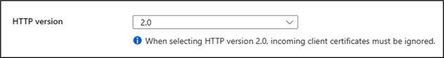
Send HTTP 2.0 Request to App Service using C#
Azure App Service supports HTTP 2.0. The major advance of HTTP/1.1 was the use of persistent connections to service multiple requests in a row. In HTTP/2, a persistent connection can be used to service multiple simultaneous requests.
This blog will demonstrate how you can send HTTP 2.0 Request to app service for testing using C#:
Step 1:
Go to > App Service > Configuration > Enable HTTP 2.0
Step 2:
Create a .Net Core Console Application / Web Application as per requirement . In this example I have taken a .Net Core Console Application:
var client = new HttpClient() { BaseAddress = new Uri(“https://<>.azurewebsites.net”) };
Console.WriteLine(“Sending HTTP 2.0 Request.”);
// HTTP/2 request
using (var request = new HttpRequestMessage(HttpMethod.Get, “/”) { Version = new Version(2, 0) })
using (var response = await client.SendAsync(request))
Console.WriteLine(response);
The HTTPClient class has DefaultRequestVersion property with which you can set the default version of the requests as below:
var SecondRequest = new HttpClient()
{
BaseAddress = new Uri(“https://<>.azurewebsites.net”),
DefaultRequestVersion = new Version(2, 0)
};
// HTTP/2 is default
using (var response = await SecondRequest.GetAsync(“/”))
Console.WriteLine(response);
You should be able to see a successful HTTP Response once the code executes:
For more information you can refer the below documents:
HttpClient Class (System.Net.Http) | Microsoft Learn
HttpClient.DefaultRequestVersion Property (System.Net.Http) | Microsoft Learn
Microsoft Tech Community – Latest Blogs –Read More

Empowering Healthcare with Innovative Solutions: A Microsoft Power Apps Project (UCL x NHS)
Introduction:
Greetings, fellow enthusiasts of technology and innovation! Today, I’m excited to share an incredible journey undertaken by our team of four UCL MSc Computer Science students. Over the past three months, we’ve had the privilege of working on three transformative projects aimed at optimizing healthcare operations using Microsoft Power Platform. Allow me to take you through the remarkable venture that is Bed Management Power Apps, TasCare, and E-Rostering Power Apps.
Meet the Team:
Before we dive into the projects, let me introduce our talented team:
1. Judy Chin
– LinkedIn: https://www.linkedin.com/in/judy-giaying-chin/
– Project team lead; Developer of TasCare
2. Lee-Yu Yeh
– LinkedIn: https://www.linkedin.com/in/leeyu-yeh-67378b20a/
– Developer of E-Rostering Manager App
3. Tania Turdean
– LinkedIn: https://www.linkedin.com/in/tania-turdean-8530aa160/
– Developer of E-Rostering Power Apps User App
4. Wenjin Yang
– LinkedIn: https://www.linkedin.com/in/wenjin-yang-28a481256/
– Developer of Bed Management Power Apps
Project Overview:
Our journey began with a mission to address critical issues in healthcare and social care management. The three projects – Bed Management Power Apps, TasCare, and E-Rostering Power Apps – were crafted to streamline processes, enhance efficiency, and provide impactful solutions to real-world problems.
Project Journey:
Navigating the intricate world of healthcare, our team encountered challenges and triumphs alike. We meticulously developed low-code, hybrid applications using Microsoft Power Apps to adapt seamlessly to mobile or web platforms. Challenges such as complex bed management systems and time-consuming shift scheduling were tackled head-on, with innovative solutions emerging at every turn. Through weekly Teams calls with our external supervisor Stephanie Stasey, we quickly understood the current hot issues in healthcare and dived into solving the problems via Microsoft technologies.
Technical Details:
In the realm of technology, specifics matter. The Microsoft Power Platform became our ally, empowering us to create solutions that are both dynamic and user-friendly. Bed Management Power Apps, TasCare, and E-Rostering Power Apps were carefully designed, leveraging the capabilities of Power Apps to bring efficiency to healthcare operations.
Using Power Apps as our main developing environment, which not only boasts the advantage of low-code but also, can easily seamlessly be combined with other Microsoft Power Platform technologies.
Dataverse, SharePoint – Seamless connection to Bed Management App live data
Power Automate – Regeneration of repeat tasks daily, weekly, and monthly in TasCare
High-complexity, low-code application – E-Rostering Power Apps
App Details & Demos:
See our project website for more details: UCL Power Apps For NHS
Bed Management Power Apps
Bed Management Power Apps address the challenge within hospitals where intricate bed management systems impede the efficiency of tasks such as patient admissions and discharges.
Github Solution: Bed Management Power Apps Solution
Demo Video:
TasCare
TasCare strives to assist workers in organizing their daily responsibilities through a mobile app, offering various features like documenting refusals and reporting incidents.
See Details and App Solution: TasCare – A Social Care Task Management Power Apps
Demo:
E-Rostering Power Apps
E-Rostering Power Apps addresses the challenge faced by hospital ward managers who spend extensive hours managing and scheduling shifts, presenting a streamlined and dependable system as the solution.
Solution: Please see our project website for details
Demo: (Admin App & User App)
Results and Outcomes:
The culmination of our efforts has led to tangible results. Whether it’s the expedited bed management processes, the streamlined social care task management through TasCare, or the simplified shift scheduling with E-Rostering Power Apps.
These application solutions are open to download and import to your own environment as solutions. See more in the individual project pages above.
Reflections
Reflecting on this journey, we’ve grown not only as developers but as problem solvers. The challenges we faced taught us resilience, adaptability, and the importance of collaboration. Each hurdle was an opportunity for personal and professional growth.
A heartfelt appreciation extends to Microsoft, Stephanie Stasey, and the NHS for their pivotal roles in our healthcare innovation journey. Microsoft’s cutting-edge Power Platform empowered us to develop transformative solutions, while Stephanie Stasey’s guidance on the healthcare sector served as a guiding light, shaping our project’s success. The NHS’s commitment to embracing technology and improving healthcare services provided us with a meaningful platform to make a positive impact. Together, this collaboration symbolizes the fusion of technology and compassion, driving us towards a future where healthcare is not just efficient but profoundly human. Our sincere thanks to these partners for their unwavering support, commitment to innovation, and the opportunity to contribute to the advancement of healthcare.
Future Development:
As we look to the future, our commitment to innovation remains unwavering. We envision enhancements, additional features, and further research to continually refine and expand the impact of Bed Management Power Apps, TasCare, and E-Rostering Power Apps. The journey doesn’t end here; it’s a stepping stone to greater possibilities.
Conclusion:
In conclusion, this journey has been nothing short of transformative. We’ve witnessed the power of technology to revolutionize healthcare and social care, making a positive impact on the lives of professionals and, ultimately, the patients they serve. Our journey has only just begun, and the potential for further innovation is boundless.
Are you intrigued by the intersection of technology and healthcare? Explore the Microsoft Learn Modules/Docs related to Power Platform to delve deeper into the tools that fueled our journey. Engage with us, ask questions, and let’s continue this dialogue for a brighter, more efficient future in healthcare.
Thank you for joining us on this adventure – together, we can shape a healthier, technologically empowered world.
Microsoft Tech Community – Latest Blogs –Read More

Contextual Risk Estimation for Effective Prioritization
Handling Cloud Posture Tasks Overload
Cybersecurity risks pose a significant threat to organizations of all sizes. As a result, security teams must be diligent in their efforts to protect their networks and data from potential breaches. However, with the increasing complexity of the digital environment and the expanding attack surface, security teams are faced with more and more tasks to improve the organization’s posture as well as investigating potential incidents. This can lead to critical security risks being overlooked or delayed, leaving organizations vulnerable to cyber-attacks. It becomes increasingly more important to estimate the risk created by the security issues in the environment’s configuration and to prioritize their mitigation correctly.
Prioritized cyber risks allow security teams to focus their efforts and resources on the most critical threats, ensuring that they are addressed promptly and effectively, which ultimately helps to reduce the organization’s overall risk profile.
Basic prioritization systems assign a static severity rating to each issue, a rating that is determined at the issue’s definition stage. This rating is based on an assumed or estimated potential impact of the threat. Devices vulnerable to the same vulnerability are evaluated to be of the same severity whether the vulnerable resource is of high business criticality and exposed, or it is an isolated insignificant resource vulnerability which cannot be exploited. That is to say, the specific details of an issue’s instance are not considered which is a significant shortcoming.
A well-established concept in risk assessment involves the dependence of risk on two critical components: the likelihood of a successful attack and the impact that such an attack can have. The relationship is frequently represented by the formula Risk = Likelihood × Impact.
More sophisticated and informed prioritization systems look further than the issue type but also the contextual information of each manifestation. It includes considering the impacted resource criticality, likelihood of exploitation, and other factors to estimate the risk posed by an issue correctly. In this blog post, we introduce a new framework for methodic estimation and scoring of risk.
The framework is based on contextual information, and we demonstrate how this risk estimation is used to prioritize the mitigation of security issues found in the environment. The risk calculation process, we consider both likelihood and impact, recognizing their significance in evaluating and managing risks effectively. By thoroughly assessing these factors, we aim to make informed decisions and develop strategies to mitigate potential threats and vulnerabilities.
Microsoft Defender for Cloud has recently introduced a new feature for Defender CSPM helping customers to rank the security issues in their environment configuration and fix them accordingly. This feature is based on the presented framework and enhances the risk prioritization capabilities of Defender CSPM.
From Concept to Reality: Prioritization Concepts
Overview
The framework enhances the basic severity score of an issue by factoring in the likelihood of a successful attack and its potential impact, empowering security teams with precise task prioritization for improved accuracy and effectiveness. The high customizability and extensibility make it suitable for any product to create prioritized task lists, whether security-related or not. It allows the incorporation of scenarios and contextual information specific to each product’s area of expertise. By empowering end-users to define the value of assets and behaviors, they have the freedom to adjust the prioritization according to their preferences. This approach enables organizations to enhance their overall cybersecurity posture and effectively secure their resources.
Prioritization is accomplished in several steps:
Security issues are enriched with contextual information.
The security issue is scored using a new method, described below.
Issues of the same risk type and security score form a group.
Groups are prioritized in descending score order.
Within each group items are sorted more precisely. This process is discussed later in this post.
In the following sections, we will explain in detail the core concepts of the new framework: security issues, contextual information, contextual security issue (CSI) and the contextual security matrix (CSM).
Security issue (SI)
The term “security issue” refers to the type of fault that requires attention, and may be indicative of increased likelihood of a successful attack, increased impact, or both. In Microsoft Defender for Cloud issues are surfaced as recommendations, which are actions that should be taken to resolve the fault and improve the overall posture and security of the environment. An issue may be realized in multiple ways and aspects. As a result, several recommendations can be an indication for the same issue. For example, both “Machines should have vulnerability findings resolved” and “SQL databases should have vulnerability findings resolved” point to the same security issue: a resource is vulnerable (and therefore, should be patched). Issues are not limited to the cloud: a vulnerability on an on-premises computer is also afflicted by the same issue. Some of the key issues in cloud environment are “Unnecessary internet reachability”, “excessive permissions”, and “vulnerability”.
Contextual Information
Contextual information is any information that affects the estimation of the hazard caused by a security issue. Contextual information could be about the methods and feasibility of exploitation of that issue, about the level and type of risk to the organization if a resource is compromised or information that may indicate an immediate intent, previous or current attempts to exploit the issue.
Like SI, contextual information could be related to increased likelihood or impact. For example, the use of a common username for authentication creates a risk as it could be a target for a password brute force guessing attack. The impact of such an issue is much greater when the asset the user has access to is the intellectual property of the organization than if the user can only access an isolated virtual machine. A resource’s exposure to the internet enhances the risk that a vulnerability on a resource would be exploited, and therefore it is crucial information to evaluate the urgency of patching the vulnerability. It might be more urgent to handle a configuration issue of a running VM than an issue concerning a shutdown VM or prioritize a resource that is known to be a target for past attacks.
Contextual Security Issue
A Contextual Security Issue (CSI) is a security issue enriched with contextual information.
Consider, for example, a vulnerable VM. The vulnerable VM poses a “Security Issue” that requires remediation. If the VM is exposed to the internet, it increases the risk of exploitation by an external attacker and therefore the internet exposure is considered “a contextual information”. Similarly, if the VM stores credentials to a critical asset, the stored credentials are also considered contextual information as they can be used to move laterally and compromise the critical asset. When the issue (vulnerability) is enriched with contextual information it forms the CSI: “Internet exposed vulnerable VM containing sensitive data“.
In certain scenarios the internet exposure itself may be a security issue, certainly the stored credentials are a security issue. Indeed, an issue could serve as a context for the evaluation of another issue’s risk. To summarize, a CSI expresses how the affected resource can be reached, the risk in compromising the resource itself, how the issue can be exploited and used to proceed to further compromise resources and the damage that may be caused.
The Contextual Security Matrix and CSI Score
So far, we have explained the significance of the context in which the issue exists. Let us examine how contextual information influences our risk estimation. Consider a resource vulnerable to remote code execution. We want to estimate the risk to the resource and environment and prioritize it compared to other issues in the queue. The contextual information that the resource is currently running, indicates that the vulnerability is in increased risk of exploitation. Consequently, this leads to an elevated risk evaluation. Let us also consider a resource that is not encrypted at rest. The risk created by the lack of encryption does not vary much whether the resource is running or not. We see that the same context may be insignificant to some issues, and incredibly significant to another. The CSM is a framework for quantifying the CSI security risk based on that understanding. The matrix reflects the degree a security issue risk increases or decreases when it occurs within a specific context.
Fig. 1: Contextual Score Matrix structure
The CSM consists of columns representing the different security issues, each assigned a “base score.” The rows correspond to potential contexts. The matrix’s cells indicate the differential score for a specific issue (column) considering the given context(s) (rows). To calculate the CSI score, the base score of the issue is summed with the applicable contextual differential scores.
The following example demonstrates the calculation of a CSI score for a vulnerability on an exposed VM that has permission to a critical asset. To calculate a CSI’s security score, we refer to the issue’s column in the matrix. We sum the base score and the values of the contexts included in the CSI. The score for the issue (i.e., the vulnerability) in the context of the applicable contexts (exposure and access) is calculated to be 13=5+(3+5).
Fig. 2: Vulnerable Exposed VM with permissions to a critical asset
The framework is extensible and adjustable. Organizations can add columns to the matrix to account for issues that are not currently considered or replace an issue with multiple more specific issues. Contexts can also be added to account for additional information if such is available. MDC prioritization is criticality biased, that is, it prioritizes protection of a critical asset over multiple non-critical assets. By adjusting the matrix weights, organizations can create a preference or a bias that better fits their needs. Contexts in the matrix may be added to support the highlighting and suppression of certain resources. This can be achieved by adding a flag context to increase the score or a flag context that reduces it for uninteresting resources. For example, a honeypot or a dev device that is deliberately left weakened.
Primary Group
The previous section explained how a CSI score is calculated. A security issue that is a part of multiple CSIs will be scored for each CSI, i.e., a list of CSI scores is calculated for it. The security issue is finally scored with the maximal CSI score on its list. This score is the issue’s Primary Score. This scoring method is where the emphasis of business criticality over the number of resources is introduced. Issues of the same primary score and issue type are grouped into a Primary Group. The primary groups are prioritized from the highest score to lowest.
Secondary Prioritization
The primary prioritization described above is criticality biased in the sense that it prioritizes security issues that expose sensitive and important resources over those risking multiple less significant resources. We prioritize one crown jewel over a stack of rocks. The complexity of exploitation of resources is considered: when a misconfigured resource is identified the primary prioritization looks to find other resources that could be “easily compromised” and may allow up to one “complicated step”.
The secondary prioritization prioritizes within the primary group, and prioritizes issues exposing more resources over those who expose fewer, and prioritizes simple exploitation routes over complex ones. This prioritization cannot result in an issue “escaping” the primary group.
Several parameters are used to determine the secondary prioritization.
The list of compromised resources: an issue that creates a risk to a greater number of resources will have a higher risk estimation score. Since we value criticality, we promote first based on the number of high-importance resources, if these match we prefer the one that has greater number of less-important resources
If several path exist that lead to similarly critical resource the simple CSIs are promoted over more complicated ones. This is achieved by assigning a decay factor, a value between 0 and 1, to each step that propagates the foreseen attack from one resourceidentity to another. The easier it is to transition to the next resource- the higher the factor. For example: using clear text credentials on a machine to log to a resource is easy, therefore the factor is high, say, 0.9.
Using a vulnerability to stealthily take hold of a resource requires a more skilled attacker and the factor would be lower, 0.4. From this factor rises the definition for “easily compromised” and “complicated step” – steps with decay factor higher then 0.5 are considered easy, lower are considered difficult.
The score of the CSI is multiplied by its’ steps decay factors, reducing the score of more complex and longer path over shorter and simpler ones.
Figures 3,4: Step for posture management task prioritization
Summary
The introduced framework is a new method that was developed to evaluate risk and prioritize the tasks needed for the strengthening of the environment configuration and posture. Using this framework, issues can be addressed in a manner that best serves the security needs of the organization, allowing for better management and quicker improvement and reduction of attack surface. The method emphasizes critical assets and prevents multitude of less significant issues from overshadowing the crucial and immediate threats. The framework is flexible and can easily be adjusted and extended to include specific or new scenarios.
Appendix 1: Issues
Software vulnerability
Description
A resource may be at increased risk of being compromised, attacked, or exploited due to a software flaw.
Examples
A server is vulnerable to Log4Shell vulnerability (CVE-2021-44228), increasing the risk of exploitation by a remote malicious code execution.
Anonymous access
Description
A resource can be accessed without being required to provide identifying information, allowing untrusted actors to access data or compute resources and potentially do harm.
Example
Storage resources open to public may lead to unauthorized access to sensitive data, as well as data breaches and corruption. Additionally, public storage resources may be used to spread malware.
Excessive permissions
Description
An identity is allowed to access more resources than is necessary for its intended function, providing opportunities for malicious actors to gain access to sensitive data or systems.
Example
Simple user that has subscription permission,
A service account that only needs “read” permission to a database but is also granted “delete” permission may be used to corrupt the database, if compromised.
No MFA
Description
Multi-Factor Authentication (MFA) is not enabled for users of certain type. A user without MFA enabled is at a higher risk of having their account accessed by unauthorized individuals, such as through phishing attacks or password guessing.
Example
A company that only requires employees to use a username and password to access their email accounts.
The Target data breach of November 2013 started when attackers managed to steal a third-party contractor’s password through a phishing attack. Since no MFA was required, the attackers were able to use the stolen credentials to access Target systems.
Default account
Description
The use of a preconfigured user account in a system or application that has a default username and password. Actors may be able to use guessed or known default usernames and passwords to gain unauthorized access to sensitive data or system.
Example
Devices are often provided with default usernames such as “root” and “admin”. The Mirai botnet was able to spread by brute-forcing default usernames and passwords on Internet of Things (IoT) devices, disrupting major websites such as Netflix, PayPal, and others.
Usage of local Identity services
Description
Authentication and authorization should be managed by the central identity provider since it allows for more granular control over which resources and systems each user can access.
Example
Use Azure Active Directory authentication for Azure Kubernetes Service clusters.
Privilege escalation
Description
The resource is using a risky configuration that might allow privilege escalation. If compromised, an attacker may gain higher privileges and potentially get full control over the resource.
Example
A container that runs as a privileged container allows a container to access host resources including modifying the filesystem and gaining elevated privileges.
Unnecessary internet reachability
Description
The resource can be reached from the internet, either directly by having a public IP or due to insufficient network restrictions. This can be a security risk because it exposes the resource to potential attacks and unauthorized access attempts.
Example
A virtual machine listening on port 3389 (RDP) and is directly accessible to the internet may be targeted and exploited as an entry point to the network.
Unencrypted communication protocols
Description
Encrypted protocols should be used for traffic over the internet. Encryption ensures that only authorized parties can read your data if someone intercepts it as it travels over the network.
Example
Web applications should use require HTTPS using TLS 1.2 or higher than HTTP.
Poor integrity
Description
Software integrity refers to the trustworthiness of software and the confidence that it is genuine and will perform as expected without any malicious or unintended behavior.
Example
Linux virtual machines should use signed boot components. Unsigned boot components are exposed to tempered and backdoored software versions.
Data Loss and corruption
Description
Measures should be taken to reduce the risk of accidental data loss or corruption.
Example
Enabling deletion protection for resources reduces the risk of accidental deletion and loss of data.
Sanitation
Description
Refers to the process of deletion or removal of unnecessary resources and accounts to reduce attack surface and prevent unauthorized access.
Example
Blocked accounts with high privileged permissions should be deleted to reduce attack surface.
Appendix 2: Contexts
Issues, by definition, indicate a weakness in the environment, and therefore every issue may also add context to other issues found. Other than the issues contexts include:
Contains sensitive data
Description
The resource contains sensitive data, such as PII (personally identifiable information), network configuration information or credentials such as usernames, passwords, keys that if obtained by unauthorized individuals could be used to access other systems.
Example
A storage resource contains employee’s personal information such as social security number and credit card number.
Resource importance
Description
The resource is of high business criticality. This context may be based on end-user input, allowing them to adjust and promote assets and behavior of interest.
Example
A subscription owner of an Azure subscription, an individual or managed identity, has full administrative access and holds the highest level of authority over the resources and services within that subscription. If the Azure subscription owner account is compromised, it poses significant risks to the security and integrity of the Azure environment. The compromised resource can be used to gain unrestricted access to any resource within the subscription, leading to data breach, account takeover, resource abuse (crypto-mining), allow the attacker to achieve persistence and undermine compliance with regulatory requirements and industry standards.
Access to a resource
Description
The resource can authenticate and has permissions to another resource, either by its assigned identity and permissions, or by utilizing credentials found on it.
Example
A VM that can authenticate as a managed identity that has permission to the subscription.
Is running
Description
The resource is currently running, turned ON.
Example
Indicates that a resource, e.g., Kubernetes cluster, is in a running state.
Cross cloud
A resource maintained by a cloud service provider can be used to compromise a resources maintained by another cloud service provider.
Example
An shh-key found on an AWS EC2 instance that can be used to authenticate to an Azure VM
Highly likely to be under attack
Description
There is an indication on an ongoing attack on the resource.
Example
There are recent alerts for RDP BF activity on the VM.
Successfully compromised resource
Description
A resource that has been successfully compromised and is therefore untrusted.
Example
There are recent alerts for RDP BF activity on the VM resulting in a successful login.
Microsoft Tech Community – Latest Blogs –Read More

Consolidating CSV results files in Azure Load Testing
Azure Load Testing (ALT) provides a rich and consolidated dashboard to analyze your load test results. However, you can also download or export the test results, build your own dashboards and reporting, for example, using Microsoft Excel or Power BI. You can also use JMeter backend listeners to write the results to a data store of your choice and analyze the data.
When you use the download results option, the ALT service splits the results into one CSV file per engine. This ensures that the file size is not huge, and it is easy to open the files in tools like notepad, excel to analyze the data. In cases where your input data is split across test engines, you can pick the results file for a specific engine and analyze.
If you want to get one consolidated view of the test run results in a single file – to compute aggregate values of response time across all the requests, to calculate the number of errors of a specific type for a request etc., you will have to go through a few manual steps to extract the zip file, open each CSV and copy the data into a single file. In this blogpost, we will walk you through two ways in which you can leverage automation for this scenario.
Download the results and consolidate into a single CSV file. You can use this option if you wish to automate the results download step as well. We will demonstrate this using a Python script.
Extract the downloaded Zip file and consolidate into a single CSV file. This is suitable if you have already downloaded the results file and you do not want to use any ALT APIs/SDKs for this automation. We will demonstrate this using a PowerShell script.
Download the results and consolidate into a single CSV file
In this approach, you can provide the test run ID as the input and use the Azure Load Testing APIs/SDKs to download the results zip file and then extract it and consolidate the results.
For this blogpost, we used the ALT SDK for Python to create a Python script that does the following:
Download the results zip file using the test run ID.
Unzip the file to a local directory.
Open each CSV file and add the engine number as an additional column.
Copy the data from each CSV file into a single consolidated CSV file.
Save the consolidated file to the same directory.
To try this out for your test runs,
Download the script.
Update the config file to provide the inputs related to your subscription and your Azure Load Testing resource.
Run the script to perform the five steps described above.
The same can also be achieved by using the REST APIs or the SDKs for .NET, Java and JavaScript.
Extract the downloaded Zip file and consolidate into a single CSV file
If you have already downloaded the results zip file to your local directory, you can skip the step to download the results using ALT APIs/SDKs in your automation script and just perform steps 2 through 5. You can use this PowerShell script to achieve this in the following steps.
Download the script to the same directory where you have the results zip file. If you choose to run the script from another directory, update the script directory path.
Run the script to extract the zip file and create a consolidated CSV file in the same directory.
To summarize, we have seen two approaches to leverage automation to simplify the process of consolidating the results from an Azure Load Testing test run into a single CSV file.
If you haven’t tried Azure Load Testing yet, create an Azure Load Testing resource and get started with your first test run in a few minutes. Let us know your feedback through our feedback forum.
Happy load testing!
Additional resources:
Azure Load Testing resources: https://aka.ms/MALT-resources.
Previous blogposts on Azure Load Testing here.
Microsoft Tech Community – Latest Blogs –Read More
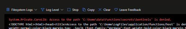
Key Vault policies affecting your Logic App Standard functioning
Sometimes we get cases that are not usual, so it’s always nice to document our findings, so that you may also investigate and solve your issues faster.
This article shows how Key Vault Policies may affect the functioning of a Logic App Standard, the troubleshooting steps and how to fix it.
Background
Logic App Standard works with many resources all together and as you know, it has a specific connection to the Storage Accounts and Fileshares, where it stores the main files and other supporting records (like in Tables and Queues).
If this connection is broken, the runtime will not be able to load as it cannot retrieve the needed files. So, when troubleshooting these types of errors, we usually check for the typical points of failure, like Private Endpoints and Vnet integrations.
Observed errors
While looking at a Logic App Standard (LA STD), we found a common error, that is the indicator of the connection severed to the Storage Account.
Our internal tools also showed that the Logic App was not able to connect to Storage Account (SA).
We knew that Vnet integration was enabled and that the Storage Account was behind Firewall (FW) and with Private Endpoints (PE).
As part of the troubleshooting, the first steps were to check the Storage Account Firewall and Private Endpoints:
Storage Account Private Endpoint associated to Logic App Subnet
Same region
All 4 endpoints created (File, Blob, Table, Queue)
All correctly configured
Still the Logic App runtime was not loading
Network tests showed that Private Endpoint name resolution was occurring without issues, so DNS was not at fault.
TCPPing tests were also successful, from an external VM to the Storage Account.
So, when in doubt, attempt to revert to vanilla state, disable FW and PE from Storage Account and disable Vnet from Logic App. After this, the Logic App was still not loading.
Again, hostname resolution and TCPPing was OK, for the Storage endpoints.
Runtime internal Logs showed the following:
Details
Microsoft.Azure.WebJobs.Script.WebHost.HttpException : Function host is not running.
System.IO.IOException : The user name or password is incorrect. : ‘C:homedataFunctionssecretsSentinels’
Log Stream showed the following:
This error is common and not very explicit. If we just cut off the Public Access, this message will also show. In fact, this image was obtained from one POC that I built, in which I had only cut off the Public Access.
As we wanted to recover the workflow files, to create a new Logic App, the user tried to browse the Logic App Fileshare. While doing this, our user was lacking the permissions to browse the Fileshare with the Microsoft Entra authentication type, so this was not valid.
Also, when trying to Browse using Access Key, this error was shown, blade failed to load with Key vault “unwrap key” error.
This was strange, as it’s not usual to see this error.
Over at the backend logs side, Storage Operations Logs show similar issue.
Microsoft.WindowsAzure.Storage.StorageException: Unexpected HTTP status code ‘Forbidden’.
—> System.Net.WebException: The remote server returned an error: (403) The key vault key is not found to unwrap the encryption key..
Findings
Deeper investigation showed that while the Encryption to the Storage Account was active and set to Customer Managed Keys (CMK), the Cryptographic operations were not allowed, thus not allowing Storage Account access using Access Key, as the keys were being stored in Key Vault for comparison.
From the documentation, we see that the Managed Identity is required to have minimum permissions, else it will fail to access the CMK.
Customer-managed keys for account encryption – Azure Storage | Microsoft Learn
“You can either create your own keys and store them in the key vault or managed HSM, or you can use the Azure Key Vault APIs to generate keys. The storage account and the key vault or managed HSM can be in different Microsoft Entra tenants, regions, and subscriptions.
…
The managed identity that is associated with the storage account must have these permissions at a minimum to access a customer-managed key in Azure Key Vault:
wrapkey
unwrapkey
get
“
Conclusions and mitigation
Due to the Encryption of the Storage Keys and the restrictions on the Access Policies, Logic App Standard was not able to correctly connect to the Storage Account, resulting in a broken runtime.
As the Policies were enabled in the Key Vault, Storage Account access was reactivated from the Logic App side, and all succeeding tests were successful, including when enabling Vnet integration.
Microsoft Tech Community – Latest Blogs –Read More

Visualizing narrow Kusto tables with Azure Managed Grafana
A common table design pattern in Kusto is the use of narrow tables.
In a schema design, narrow tables are characterized by having a few data values colums, so for each row in a table, different types of information being stored. A narrow table can still have multiple columns that serve other purpose. For instance, columns could be present for various dimensions, such as a device or a sensor.
Let’s consider an example of a narrow table with a fixed schema. The metric column includes values like temperature, pressure, or vibration. The respective measurements for these metrics are stored in the sensor_reading_real column:
measurement_ts
device_id
metric
unit
sensor_reading_real
2024-02-27T09:17:19Z
device-1
temperature
°C
15
2024-02-27T09:20:00Z
device-2
temperature
°C
15.01
2024-02-27T09:20:00Z
device-2
pressure
kPa
10
2024-02-27T09:30:00Z
device-2
temperature
°C
16.01
The design pattern is very flexible. For new metrics no schema design change has to be made.
How to achieve having multiple metrics in one visualization, with the additional flexibility to let users select what metrics to be visualized? The envisioned outcome is a Grafana dashboard of a certain design:
Grafana dashboard – envisioned outcome
For this blog-post we are using Azure Managed Grafana for the visualization. As a pre-requisite we assume that you have Azure Managed Grafana and a Kusto database running.
In Kusto we use the following table definition to store the data:
measurement_ts : datetime,
device_id : string,
metric : string,
unit : string,
sensor_reading_real : real
) with (docstring =’narrow table with data values with datatype real’, folder =’narrow’)
The function definition looks as follows:
narrow_measurement_real
| where measurement_ts between (_from .. _to) and metric in (_metric) and device_id in (_device_id)
| summarize sensor_reading=max(sensor_reading_real) by metric, device_id, bin(measurement_ts, _bin)
| evaluate pivot(metric, max(sensor_reading))
| order by measurement_ts
}
With this we are done on the database side and can start with the setup in Azure Managed Grafana. First we will set up a connection to our KQL database (for the detailed steps, please see also the documentation Visualize data from Azure Data Explorer in Grafana ). As a connection type we choose Azure Data Explorer Datasource. For the connection setup to the Kusto database in Azure Managed Grafana you need the cluser URI (for Fabric this is the URI provided as a Query URI under the database details). We are using the current user authentication method here, passing through the current user in Azure Managed Grafana to the Kusto database. You have to make sure that the users have at least viewer-permissons on the database. As of writing this blog article current user authentication method is in experimental phase, so it is not recommended yet using this in production deployments.
The connection will look similar to:
Now we can start with the dashboard creation. In Grafana go to the dashboards menu, create a new dashboard and add a visualization, and select the data source you’ve defined in the previous step. In the query window, switch from the builder to direct KQL, as the query builder currently does not support functions.
The KQL in the query window should look like this:
let _to=$__timeTo;
let _bin=$__timeInterval; //The $__interval is calculated using the time range and the width of the graph (the number of pixels).
let _device_id=dynamic([$v_device_id]);
let _metric=dynamic([$v_metric]);
wide_measurement_real(_from, _to, _bin, _device_id, _metric)
Next, you’ll need to define the two variables referenced in the query for the drop-down selection:
for the selection of the devices (include the time filter so users can only select devices for the current time-filtering),
and for the selection of the metrics.
Apply the current dashboard configuration and switch to the dashboard settings to define these two variables as query types. Define the name, the label, select your data source, and choose Kusto Query as the query type. You can either use the builder or direct KQL entry with the query definition that looks as follows for both variables:
Devices: v_device_id
| where measurement_ts between ($__timeFrom .. $__timeTo)
| distinct device_id
| order by device_id asc
Metrics: v_metric
| distinct metric
| order by metric asc
Make sure to change the refresh to On time range change for devices if you do the time selection in the query for the variable v_device_id. Enable multi-value selection for both variables, as we want to plot multiple metrics in the chart and multiple devices on the dashboards. This is also important, as the variables are defined with the dynamic datatype, so an array of senor ids and device ids is expected.
Almost done! Here are a few more edits:
Add v_device_id under repeat options to get the timeseries per device.
Define overrides for fields with regular expressions (this requires metrics to follow certain naming conventions). This way, you can configure the metrics displayed with different units based on the name. For more information on overriding the units of the metrics, check out the Grafana documentation
Add the legend as a table with several calculations and include calculations like minima, maxima, mean values.
With this we are done, and have created a simple and very flexible dashboard! If new metrics are inserted ot the table, no change is required, you will be able to visualize them as they will appear in the dropdown list for the selection:
Grafana dashboard with the metric selection
Conclusion
In this blog article, you have learned how to use narrow tables in Kusto, how to create a function to get a wide view on a narrow table definition, and how to visualize multiple metrics in one visualization with the flexibility for users to select the metrics they want to see. You’ve also learned how to define variables in Grafana for a more interactive and customized visualization experience.
Microsoft Tech Community – Latest Blogs –Read More

Veritas offers MISA partner solutions in Azure Marketplace
The Microsoft Intelligent Security Association (MISA) is an ecosystem of independent software vendors and managed security service providers that have integrated their solutions to better defend against a world of increasing threats. Learn more about offers from MISA partner Veritas in Azure Marketplace:
Veritas Alta Data Protection (Americas): Available in the Americas, Veritas Alta provides autonomous cloud data protection powered by Microsoft Azure for workloads of any size in any environment. The solution delivers elastic infrastructure for data protection, fully managed retention services, and cost-effective automated backups for leading SaaS apps, including Microsoft 365, Salesforce, and others.
Veritas Alta Data Protection (EMEA): Available in Europe and the Middle East, Veritas Alta provides autonomous cloud data protection powered by Microsoft Azure for workloads of any size in any environment. The solution delivers elastic infrastructure for data protection, fully managed retention services, and cost-effective automated backups for leading SaaS apps, including Microsoft 365, Salesforce, and others.
Veritas Alta Application High Availability (Americas): Available in the Americas, Veritas Alta Enterprise Resiliency optimizes workload performance while delivering real-time monitoring and disaster recovery orchestration. Built on Microsoft Azure, Enterprise Resiliency uses software-defined storage to provide business continuity for your business-critical applications, enables data migration between regions, and delivers a holistic solution for high availability workloads.
Microsoft Tech Community – Latest Blogs –Read More
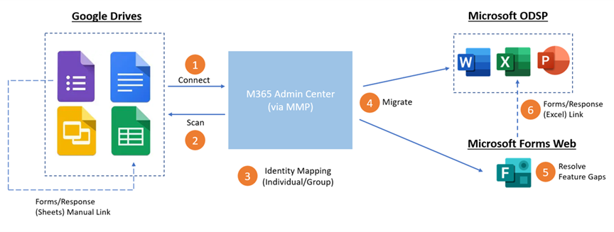
Migrate Your Google Forms to Microsoft Forms in Microsoft 365 Admin Center
Now you can migrate your Google forms to Microsoft Forms for the full Microsoft 365 experience. This feature is currently available in the Microsoft 365 admin center and is designed as an admin and tenant-level feature, enabling admins to bulk migrate their Google forms to Microsoft forms through the Microsoft 365 admin center. Individual users can then access the migrated forms on the Forms website after the migration. In the initial phrase, we’re -leveraging the existing document migration process in the Microsoft 365 admin center to support forms migration under personal Google drives. Now, let’s delve into the end-to-end process.
Google form migration E2E flow
Prepare for the migration
Users should review their Google forms and responses prior to the migration and then verify all information is intact once the process is complete.
Review Google forms before migration
Forms migration in the Microsoft 365 admin center
The admin can initiate the migration from the Microsoft 365 admin center. To get started, the admin should firstly add, select and copy the targeted drives for migration, then designate the destination storage within OneDrive. Note: it’s mandatory to specify forms destinations, either specifying individual forms destination via UX (below) or uploading CSV file for bulk. Next, they can start migrating the forms under the selected drives. Once the migration is complete, the admin can access the summarized report or download the full report to see more details in Excel.
Specify individual forms destination via UXSpecify forms destination in bulk via CSV file
Retrieve migrated forms on the Forms website
After the migration, users can go to the Forms website and find all the migrated forms in one collection (Migrated Forms from Google). The migrated forms are almost the same as before the migration, and only require minor edits before re-use. Users can view the migrated responses in Excel.
Check migrated forms on the Forms website
Microsoft Tech Community – Latest Blogs –Read More
Access Releases 9 Issue Fixes in Version 2312 (Released January 4th, 2024)
Our newest round of Access bug fixes was released on January 4th, 2024. In this blog post, we highlight some of the fixed issues that our Access engineers released in the current monthly channel.
If you see a bug that impacts you, and if you are on the current monthly channel Version 2312, you should have these fixes. Make sure you are on Access Build # 16.0.17126.20126 or greater.
Bug Name
Issue Fixed
No list of font sizes when Aptos font is selected
Aptos is the default font for controls in a new database using the recently updated ‘Office Theme,’ but the font size drop down was not displaying a list of font sizes (although you could manually type in a font size).
When a query was open in datasheet or design view, the context menu command to open in SQL View in the navigation pane would not switch the open query to SQL View
This command on the context menu was recently added to allow opening a query directly into SQL view. However, to be consistent with other commands, it now switches the mode of a query that is already open to SQL view.
#Error when using DateDiff with one Date/Time column and one Date/Time Extended column
The DateDiff function was working correctly if both arguments were of type Date/Time, or both arguments were of type Date/Time Extended but would fail to evaluate with one argument of each type.
The updated linked table manager no longer shows the name of the DSN used for a linked table
The old, linked table manager displayed this information. The new linked table manager now also displays it.
Access may terminate unexpectedly when running a macro after editing it
In some cases, after adding/removing/moving macro actions in the macro designer, then attempting to run the macro, Access would terminate unexpectedly. This no longer occurs.
F1 does not display the correct help page when used on some properties/methods of the Field2 object in the VBA IDE
F1 now directs to the appropriate help page for the following properties/methods:
CreateProperty, Expression, IsComplex, Name, Required, SourceTable, Type, ValidationRule, ValidationText, and Value.
Some valid values for the DBEngine.SetOption method have no defined constant
The following constants were added:
dbPagesLockedToTableLock, dbPasswordEncryptionProvider, dbPasswordEncryptionAlgorithm, dbPasswordEncryptionKeyLength
Subform control does not support LabelName property
The LabelName property was shown in the property sheet for every other control that supported child labels and is now present for subform controls as well.
Auto expand in combo boxes doesn’t work for list items >100 index
In some cases, autocomplete did not work for items in a dropdown list when there were more than 100 items in the list. This issue has been resolved.
Please continue to let us know if this is helpful and share any feedback you have.
Microsoft Tech Community – Latest Blogs –Read More